 Yann Guidon / YGDES
This log continues after 11. Design of the bit extraction circuit has stopped.
The last log 4. Tiling explains why the tiles are limited to 8×8, this keeps the highest luma values under 64K. We can work with a 32-bits processor
We also know that the direction of the shift must be reversed (in MSB order) to prevent nasty corner cases encountered in the original code.
The chosen approach is:
- rough (8- and 16-bits granularity) on the "stream" side (the network or filesystem)
- fine granularity (up to 16 bits shifted by 0-31 bits) for the encoder/decoder side
It should be both easy to implement with code and logic gates, in particular the byte/word insertion and extraction can be limited to a single location, which simplifies some of the circuitry (but adds one cycle of delay for the very first cycle).
The source and sink sides can work with a 16-bits wide shift register that can shift up to 32 positions (that's 4 MUX2 layers of 16 bits, at most 128 gates)
The type of truncated binary code is "phase-out", which is reversed phase-in where the lower value range uses one more bit.
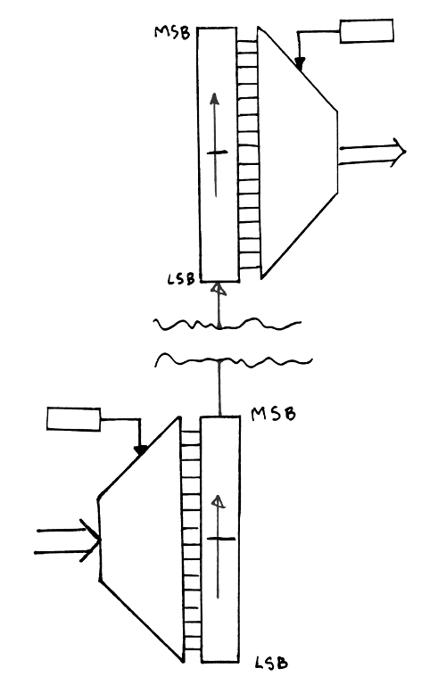
The encoder starts to put the first VLC at the "top" of the shift register. More VLC are added, at decreasing indices, until at least 16 bits have been written to the shift register. The top half of the register is then sent to the receiver, then the lower half is copied to the top half.
At the receiving end, the shift register is filled with the 2 first 16-bits words, then starts to read the bit fields starting from the MSB. When more than 16 bits have been read, the shift register is shifted by 16 bits (the lower half overwrites the higher half) then the lower half is read from the stream of words.
20170602:
Working with a given word size, I realise that one bit can be saved.
For 16-bits words, the register needs only 31 bits because the word can only be shifted by 15, the 16th is no-shift.
So the counter goes from 31 (shift register empty) down to 0 ("flush the high word, man !") and the lower half has only 15 bits instead of 16.
In hardware, the shift counter might even be stored as only 4 bits, while the subtraction would use 5 bits to detect the overflow (which triggers the emission of the word), just like a pulse-density (sigma-delta) modulator...
20170603:
test-bitstream.html contains a simple test for the encoder and decoder, without the phase-out part.
I must design the phase-out code then rewrite the routines in C.
Discussions
Become a Hackaday.io Member
Create an account to leave a comment. Already have an account? Log In.