 Jarrod
PCB's arrived, looks nice in gold :D
Turns out it's slightly smaller than a business card!
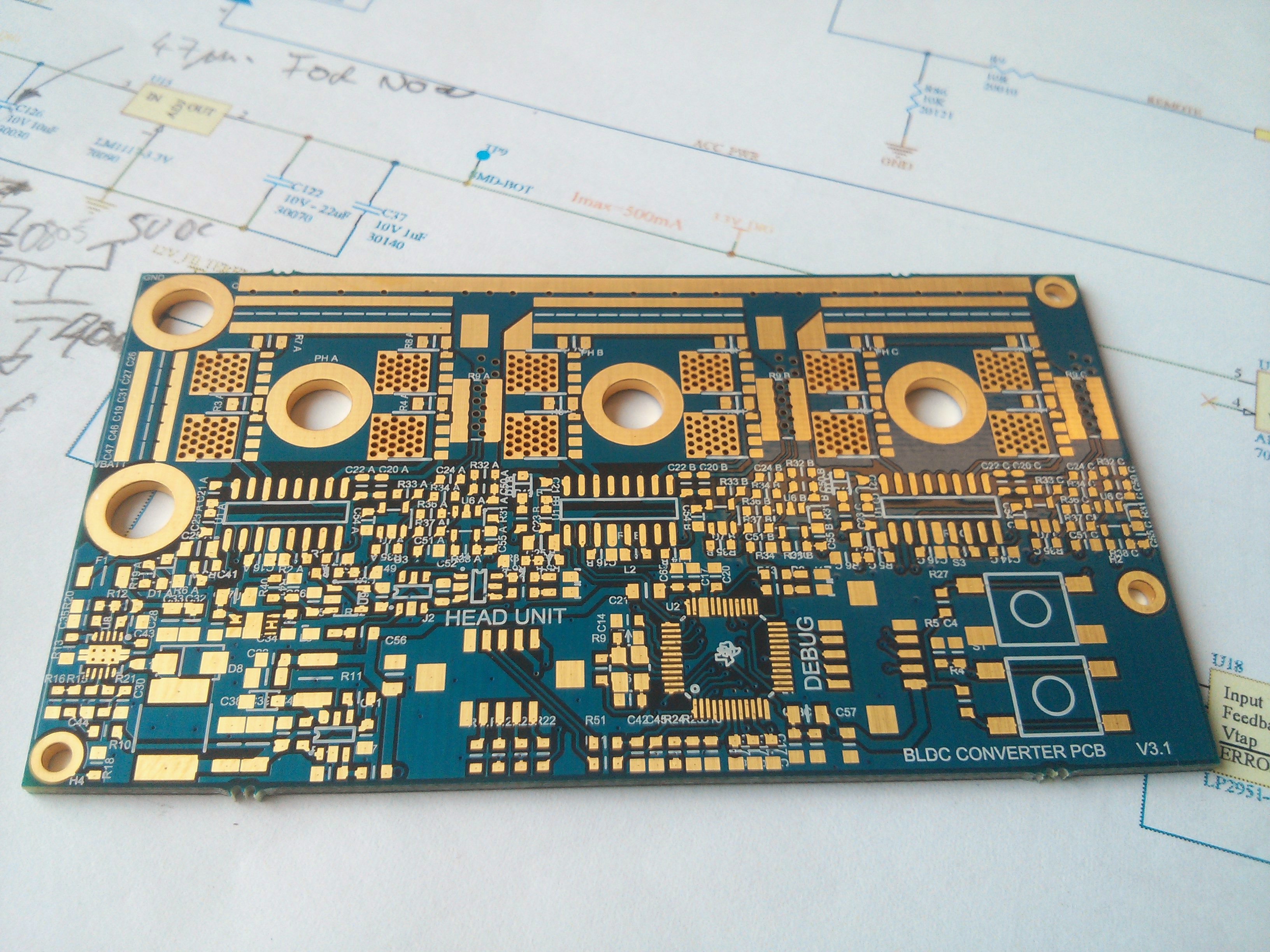
OK I messed up a few designators, was a bit of a rush to get it in the prototype panel at work (it always is)
I figured I'd take this chance to show how I've learned to bring up a circuit. first thing is always the power supplies, nothing will work without them afterall..
My preferred way of assembling prototypes like this is to coat the board with rosin flux and proceed to add solder to all pads
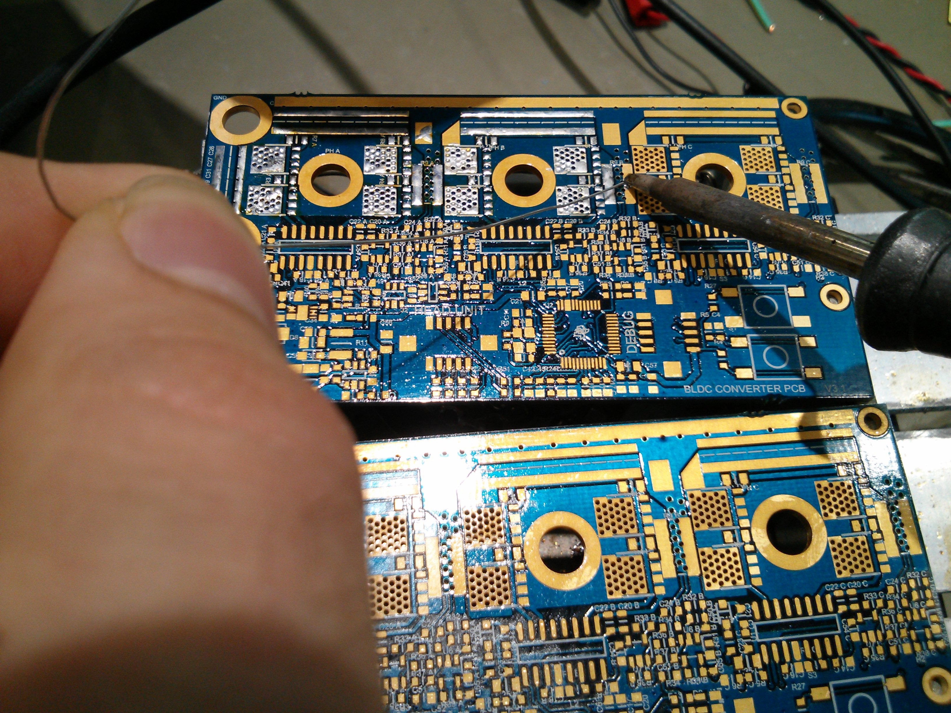
Once the pads are coated with sufficient solder, additional flux is used and a hot air soldering gun melts the solder while you place the part with tweezers, usually the amount of solder that is stuck to the pads is enough to attach the parts, if not I'll just go over them with a fine tip iron and additional solder.
So I started by populating the 10V SMPS as the other rails are powered by this, it's also a circuit that's new to me. I took values from the example circuit in the chip's datasheet and tweaked for my desired voltage. amazingly it pretty much worked first try, always nice!
I approximated the sort of load this psu might see would be <5W, or 10W when charging a phone, so 20ohm and 10ohm loads were used for testing.
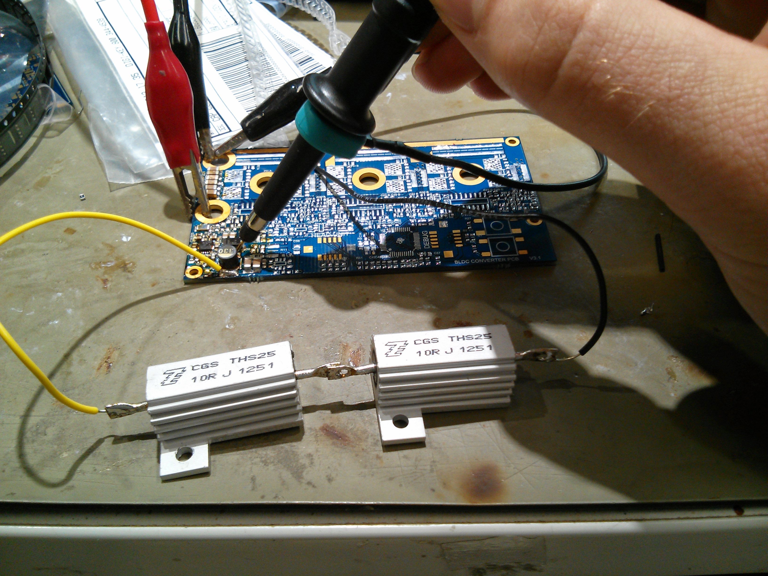
I used the power analyser at my work to check efficiency over input voltage range.
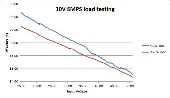
This shows that the power supply is easily capable of powering the head unit and charging a phone, efficiency does not drop as much as I had feared at full voltage. the thermal vias do their job of sucking heat away as the chip barely gets warm running at 10W. this is delivering 1A, they have rated it for 1.5A output current, at some stage I'll have to go through the maths to check if this configuration will survive that amount, until then I feel safe running it at 2/3rd current.
Next I populated the 3.3V smps for the microcontroller, this was a proven circuit and was no trouble, then the 5V linear reg and the opamp bias rail, U9. Here I realised a mistake, I really should be running all the opamps (which are used to amplify the current sense resistor voltage) at the same rail as my microcontroller, as higher than rail voltages could destroy the chip. First wire mods! yay.. I cut the VCC tracks to the opamp on each phase sense and ran some wire wrap wire to the nearest 3.3v point.
A few hours of placing parts and voila!
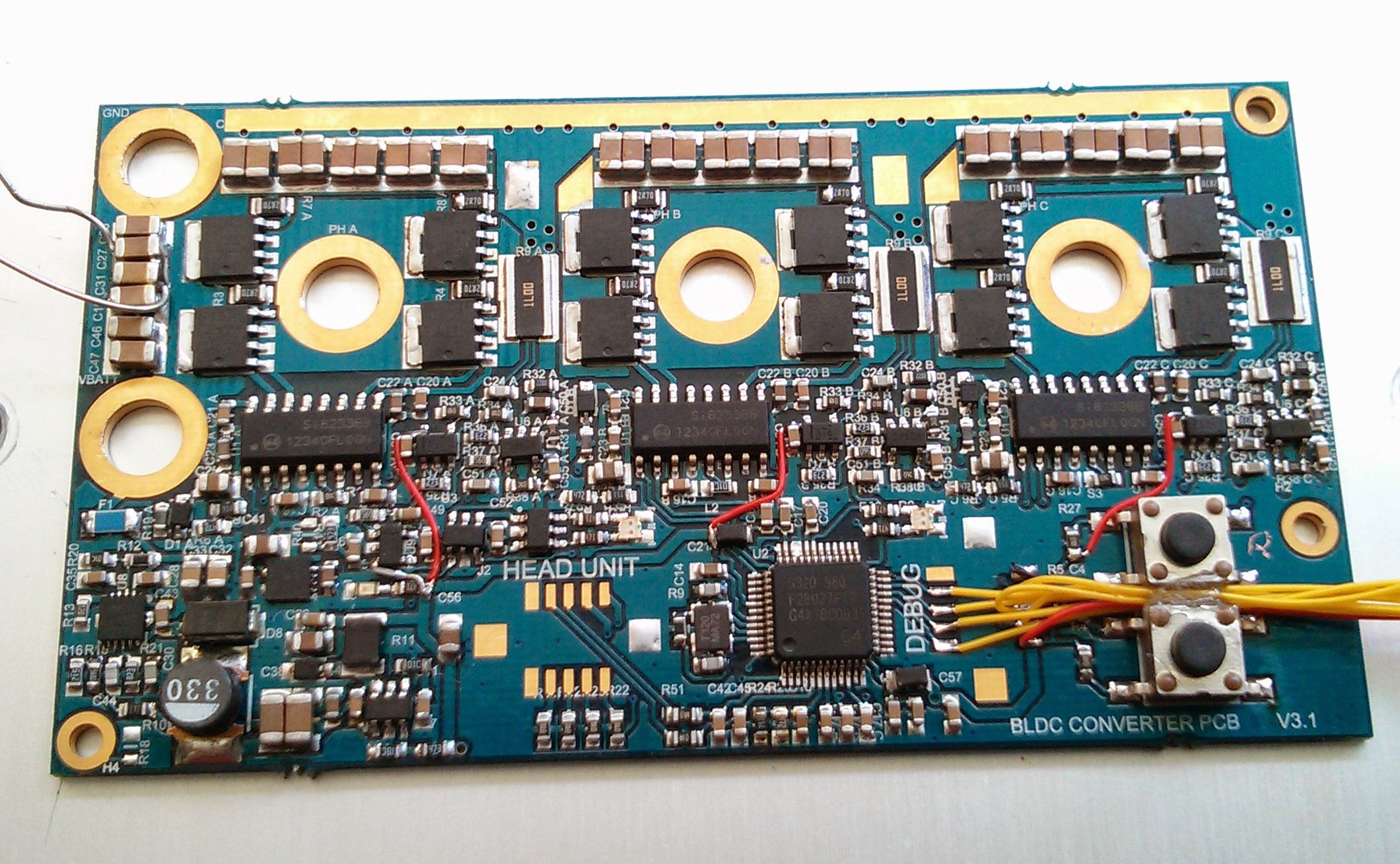
My makeshift jtag connector on the right, I forgot to order the neat little Hirose connecors I had intended to use.
Next I'll see if it will take a program.
Discussions
Become a Hackaday.io Member
Create an account to leave a comment. Already have an account? Log In.