 Jarrod
Let’s lay down some basic requirements for the power delivery side of this project:
1. It should have sufficient power to propel a light vehicle to normal commuting speeds, ebikes have become standardised at ¼ of a KiloWatt, lets go for 1KW (continuous) to cover slightly larger or faster vehicles or those with a need for higher peak power (self balancing for example).
2. Compact and light-weight. This expands the systems possible uses.
3. We want it to be efficient - efficiency can result in smaller size due to reduced heat dissipation and battery capacity requirements
4. It should work with a wide variety of motor types - e.g. a motor built into a wheel, or one which drives a chain. The physical hardware should be easy to set up, plug and play with simple configuration
Given the required combination of high power, light weight and high efficiency, we can narrow down the types of motor appropriate for this system to support.
Permanent Magnet motors are widely used in small EV’s because of their light weight and high power density, there are two types, brushed DC and brushless DC.
In brushed motors, the rotating magnetic field is produced using brushes contacting a sliding set of contacts (called a commutator), the mechanical commutator is lossy and it doesn’t present ideal waveforms to the motor’s windings. brushed motors trade efficiency and energy density for electronic simplicity.
Brushless motors are called so because they replace the mechanical commutator with a far more efficient electronic inverter, using transistors to switch the currents on and off instead. For this reason they can be made far smaller and more efficient, an obvious choice for a modern EV.
Now for some basic inverter theory. Inverters take DC from a battery or other source and turn it into an AC waveform, in this case, to drive the motor. How is it done? Using a couple of switching components to pull an output node high and low, this implementation is known as a H-bridge, we can generate a waveform by inputting a varying Pulse Width Modulated stream and averaging the output of the H-bridge. using three of these, one for each phase of the motor, a 3-phase relative waveform can be generated.
This figure shows a typical 3-phase inverter configuration and a simplified illustration of how a waveform can be obtained by averaging a PWM stream.
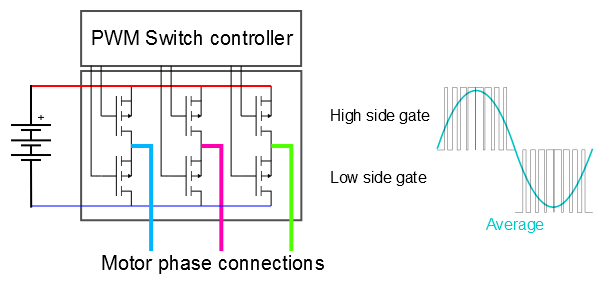
The important advantage of using a pulse stream like this is that the switching components (for example FET's in the above figure) are kept either in a low-impedance ON state or high impedance OFF. They transition through the linear range of conduction as quickly as possible, this reduces loss in the switches.
With that basic theory out of the way, Lets move on to the physical inverter implementation.
Requirement 1 is primarily a matter of choosing appropriately specced components and having good PCB layout, since this is going to be a low cost, low weight system 48V motors are commonly available and this relatively high voltage keeps the system current low, reducing resistive loss.
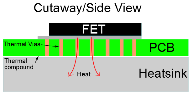
Requirement 2 and 3 can be achieved by using modern MOSFET technology, and switching them properly. we will use low Rds(on) FETs from NXP, after investigating many different manufacturers the NEXFETs from NXP seem to have the best gate charge vs Rdson - gate charge limits how quickly FET's can switch and Rds is the drain-source resistance that results in conductive losses when the device is fully on. The powerSO8 package also has excellent thermal characteristics and can be heatsunk through a viad PCB, making the layout very compact. Manufacturability is also improved over using TO220-style packages as the whole board can be made SMD then simply bolted onto a slab of aluminium as shown below:
To switch the mosfets we are using isolated gate drivers from Silabs. these chips are monsters. 4A current capability and 1000V isolation. probably overkill but we can cost reduce later ;) These will ensure the FET gates are transitioned in mere nanoseconds, wasting very little power in the linear region of the FET.
Discussions
Become a Hackaday.io Member
Create an account to leave a comment. Already have an account? Log In.
Are you sure? yes | no