I figured out that my theory-based approach (with lots of spec reading and basic tutorials) won't get the CD-player going. And people have been trough all this before me, so why reinvent the weel.
There was a bookmark in my browser, that contains most of the answers to my previous questions - ATAPIDUINO (by Carlos Durandal). How could I forget about this! I wanted to know and understand things, before moving to this already-finished arduino project. But how could that be better than studying an already working example *facepalm*!
Serial to Parallel conversion magic box
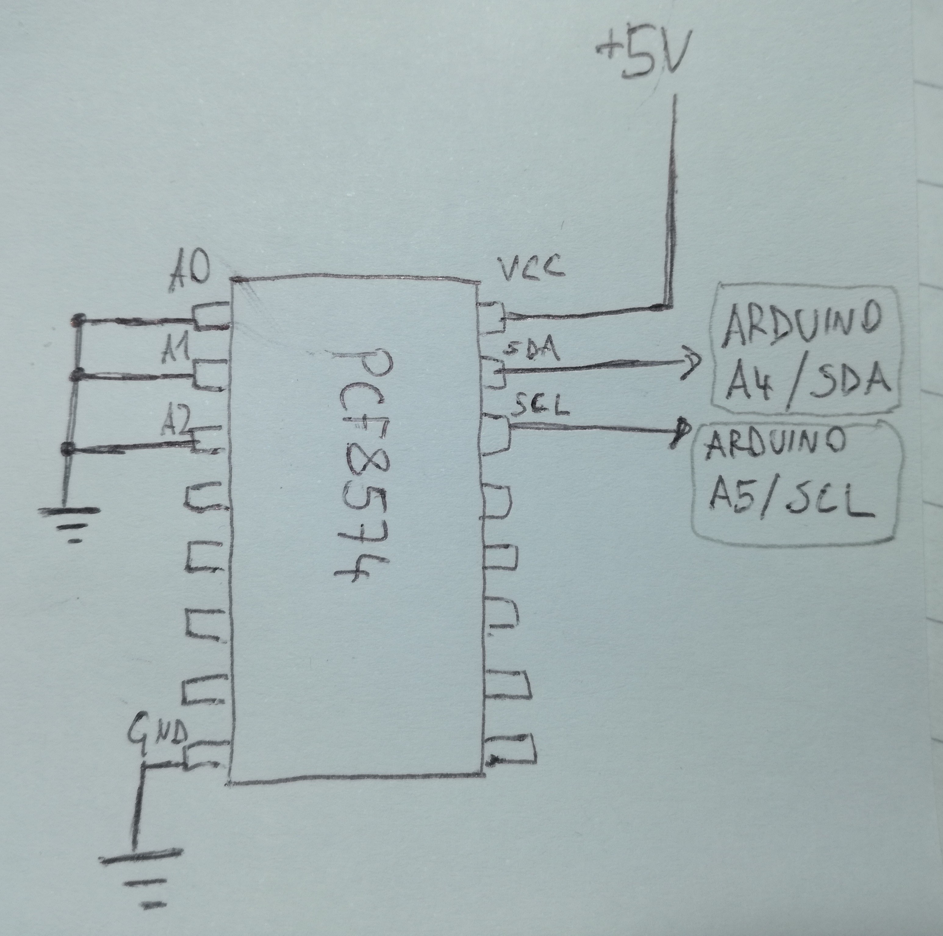
How do I connect Arduino to a 40-pin IDE connector? Connecting every arduino pin directly to IDE pin wouldn't work, I should rather do somekind of serial - parallel conversion (introduction to the topic). And that exactly what Atapiduino does, using I/O expanders for I2C bus (PCF8574).
The PCF8574 I/O expander basically recieves bits one-by-one and when it collects a byte (8 bits) it "spits them out" simultaneously, each bit on it's own pin (rough description, probably not technically correct/exact).
We send commands from a microcontroller (Arduino) to PCF8574 I/O expanders using I2C protocol (lots of good tutorials about I2C on yt and google).
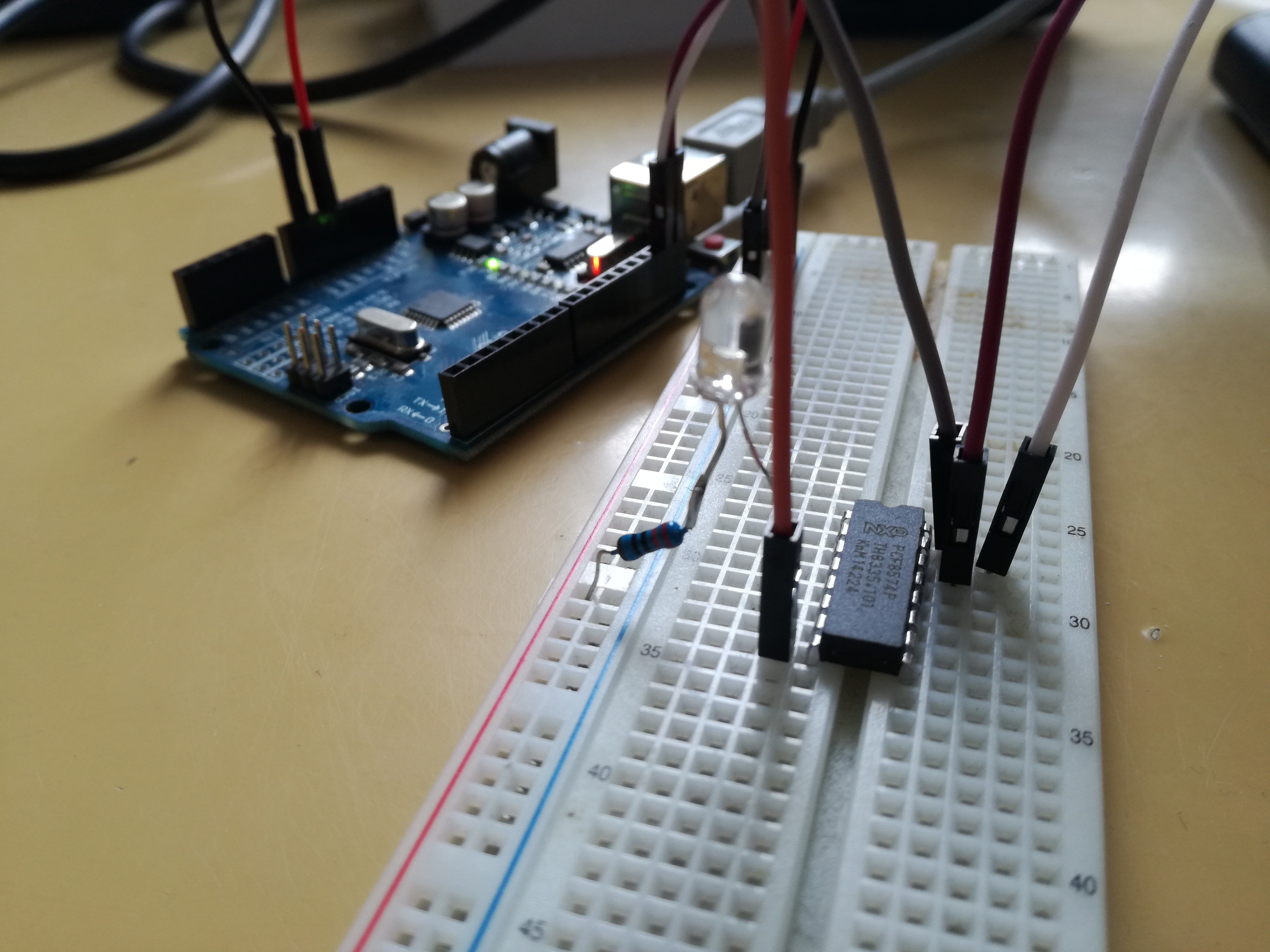
I first tried connecting an I/O expander to an arduino and a LED, to learn how to work with theese.


Only thing you have to set before toggling pins on/off is the address of the device- datasheet (chapter 7 my case) describes this well. And the I2C serial communication things like start & stop bits, parity, baud rate etc. - you don't have to worry about theese, if you use arduino. The Wire.h library handles all this, so all you have to do is begin communication, set the address of the slave device (the I/O expander is slave, arduino is master) and start sending bytes.
#include <Wire.h>

void setup() {

  // Start I2C interface
  Wire.begin();

  // Set parameters for communication with our PCF8574 I/O expander.
  // We've set all the address pins (A0, A1, A2) low,
  // so our I/O address is 0x20h according to the datasheet.
  Wire.beginTransmission(0x20);

  // Byte we want to send. Bits are mapped to pins P0 -> P7
  // (each pin represents one bit of a byte).
  // E.g. 0x07 (0b00000111) sets pins P0, P1, P2 HIGH and others LOW.
  Wire.write(0x07);

  // Transmit / send the byte
  Wire.endTransmission();

}

void loop() {
}
You can test if your circuit works, by measuring voltage on the P0->P7 pins of the I/O expander (one voltmeter probe to GND and another to one of the P0->P7 pins). For our example P0, P1 and P2 should be HIGH (5V), others LOW (0V).
I was struggling with my I/O chip for hours, only to realize that it didn't work. So be aware that ebay stuff sometimes doesn't work (lesson learned the hard way). Yay :)
Any electrical engineer wants to comment the use of PCF8574 in this application? If you had to connect a microcontroller to a 40-pin IDE device, what would you use? What would be the simplest component to use in this application? What would they teach you in school? Which chip would they use in industry?
 jurc192
Discussions
Become a Hackaday.io Member
Create an account to leave a comment. Already have an account? Log In.