I had some time, so I looked for a new drive. Later I find two lenze 8200 vector drive, one of them was actually good, but the other one, which one was a 0,75kW modell, it was bad.
I bought both of them, and sell tested the good one, after them sell that for the price I bought the two drive, so I was at my money actually so I was not to worry about if I could not repair the other one.
Lets start the repair storry of the bad drive:
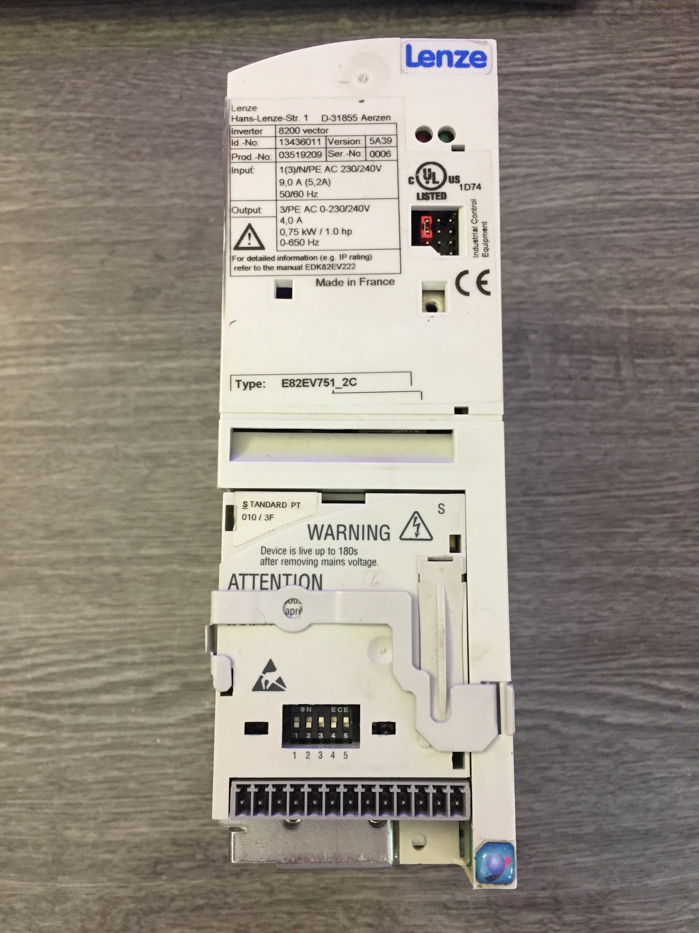
I knew this drive was repaired before, because it was a repair company warranty sticker on it, but I was not to afraid of it, because I knew the company and they was not the best. The Lenze 8200 vector drives has a separated I/O modul, which I got with the unit, so I was lucky this time.
As you can see it is a 3 phase 230V input modell, and it is capable of driving a 3 phase 0,75kW motors.
For first time I looked if it hase any burn or smoke marks on the case, but this one was okay.
It is important, you have to check the input rectifier diodes and the IGBTs before you can connect any power to it!
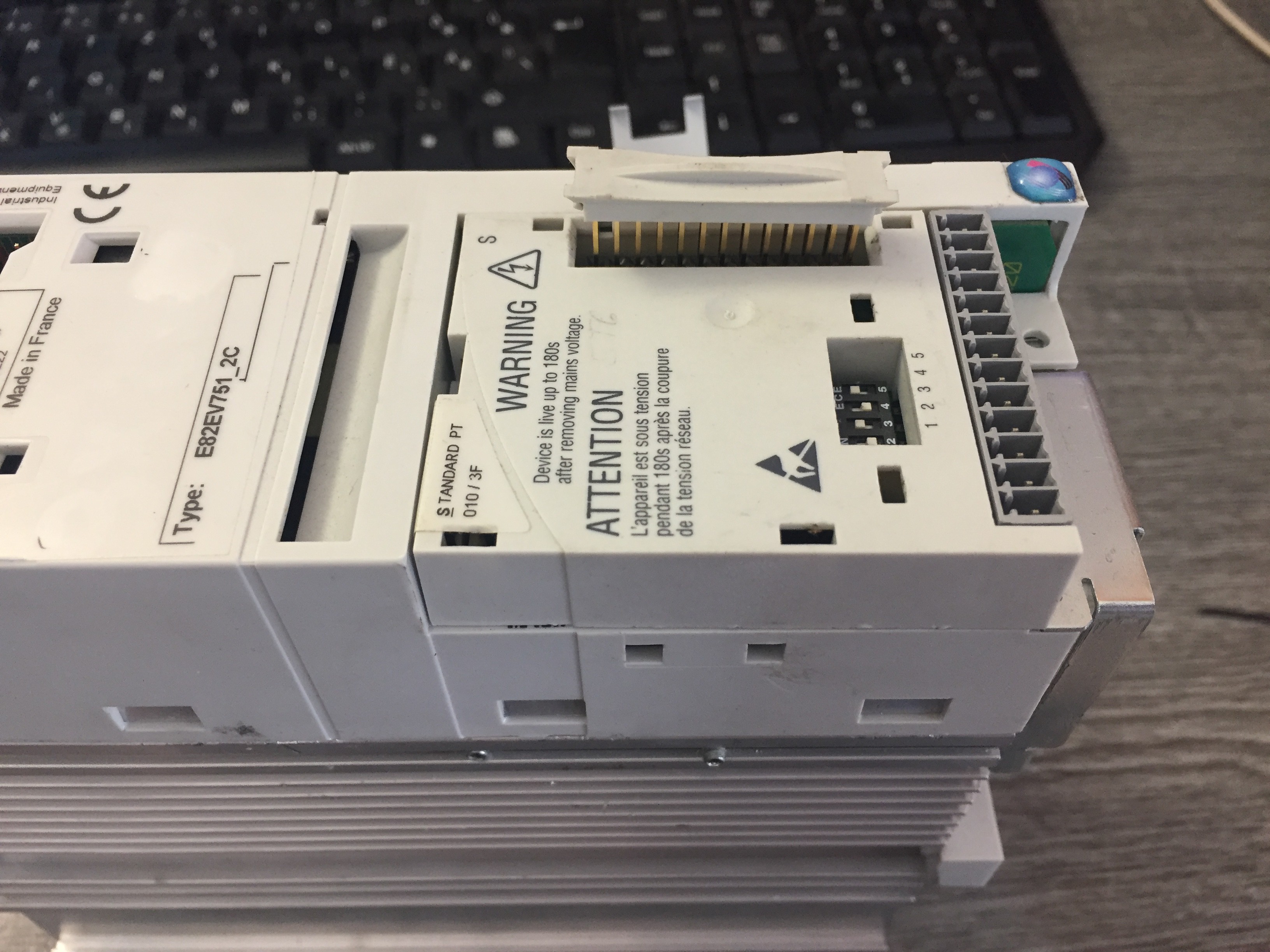
This drive has all the main connections on the botton and the top.
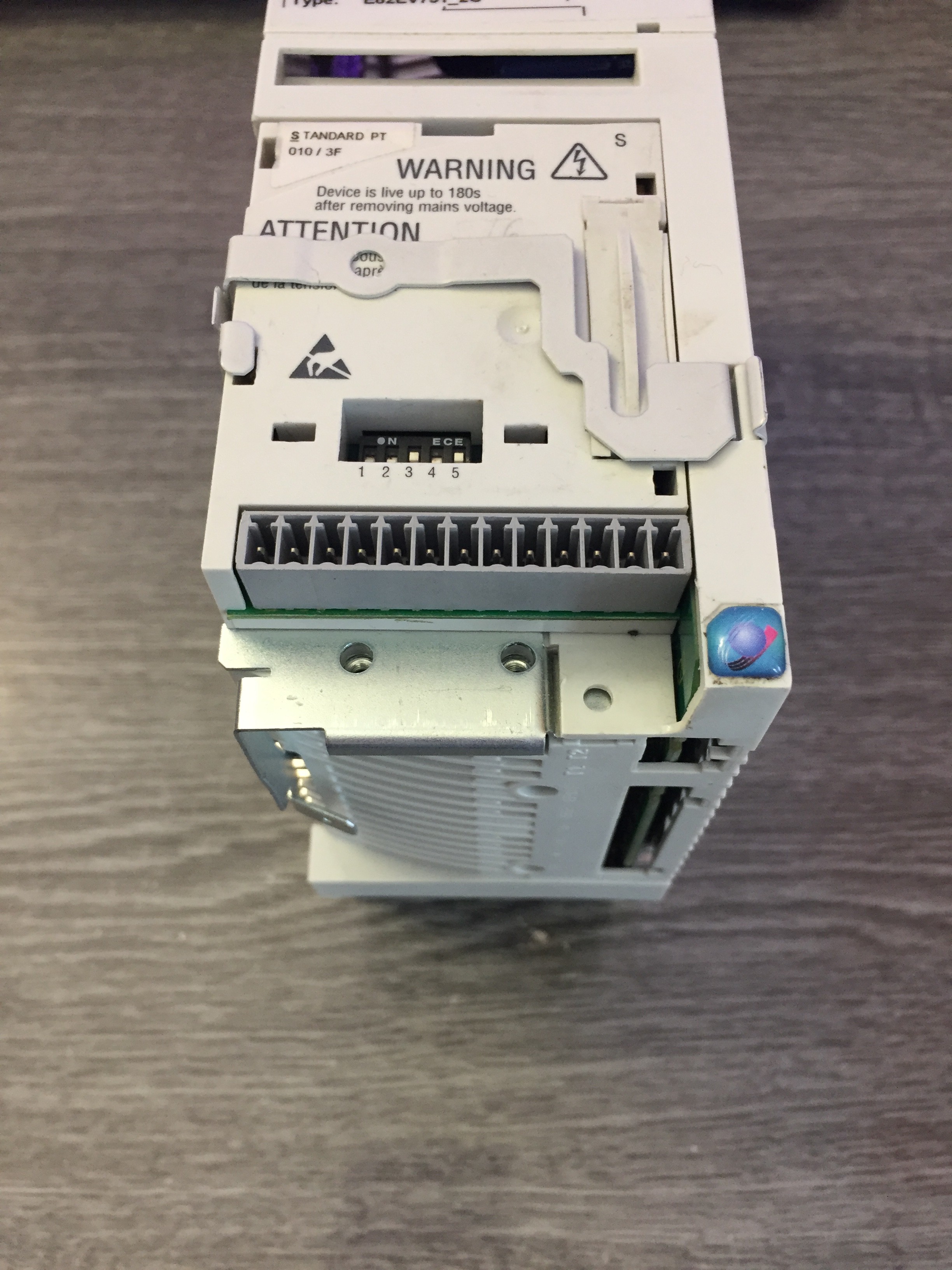

First you need a mutimeter with diode check mode and you have to find a way to measure the DC-BUS sometimes they make a connection for those like on this device marked like UG+/UG- . If you do not have those points you have to disassembly the device first.
If you have those like I had, you can check the rectifier diodes if you put one multimeter probe on the DC-Bus (UG+/UG-) and the other you put on the input, marked with R-S-T or L1-L2-L3 you shoud get a measurment like 0.5 or 0.6 V, if you have any continuous beep you have a shorted diode, so do not apply any power to the drive before you fixed it.
You can chech the output the same way, but you measure the output marked with U-V-W and you shoud get as well 0.5-0.6V measurment on the multimeter. If you get 0V- you have a shorted IGBT, or if you have nothing you try to switch the probes if it is still nothing you have a bad IGBT as well.
In my drive I measured both the inputs and the outputs, I got for shorted rectifier diode at the input, but no damage at the output side, so I was lucky, because I knew it would be a easy fix for me.
Next step was, disassembly the case.
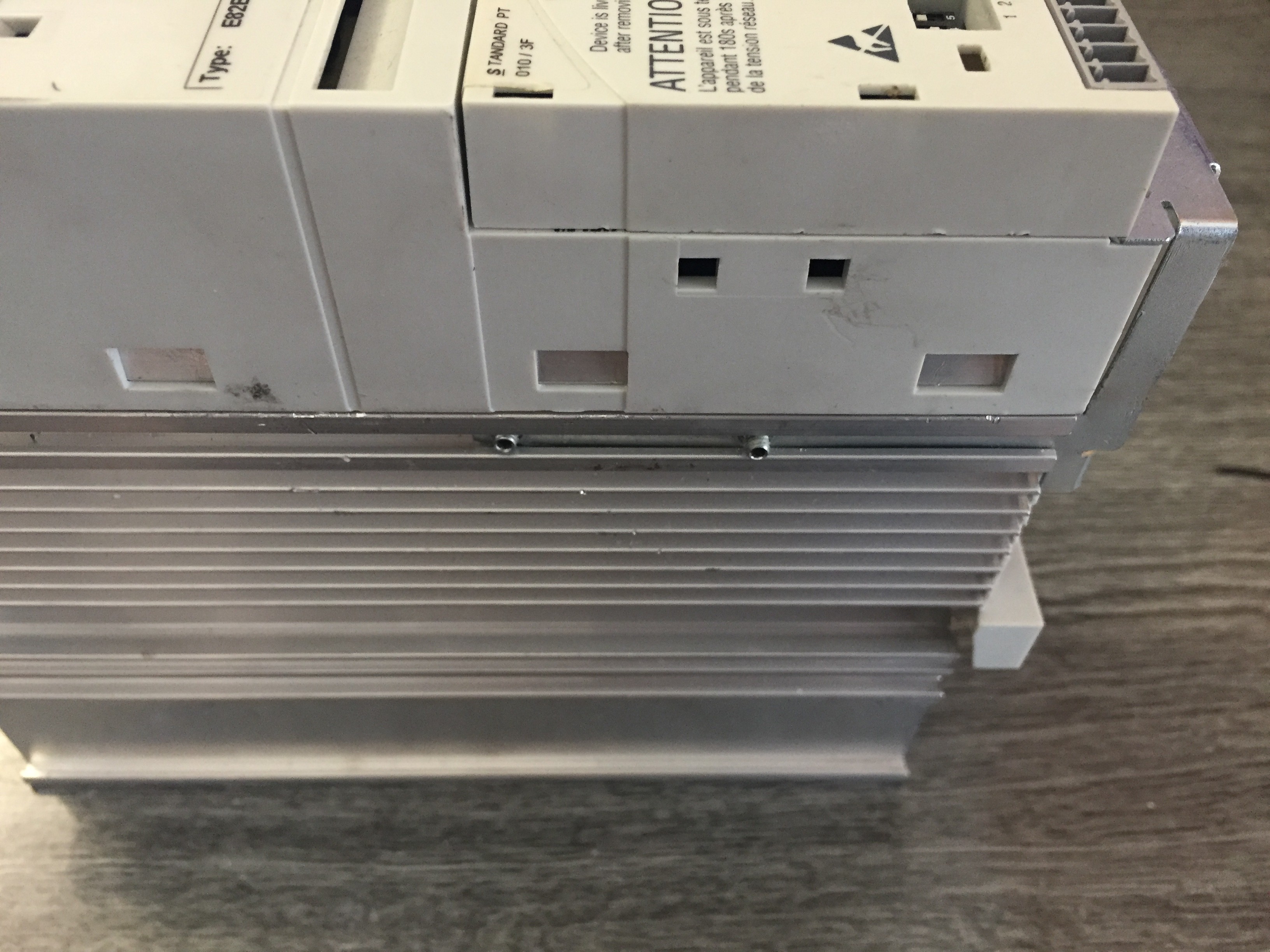
On the smaller Lenze vector drives you first have to unscrew those two screw first, on the left side on the drive. After that you can pull backwards that metal.
The second step is only if you have a I/O modul installed, you have to pull up the header with a flat screwdriver, after you can pop up the modul.
The third step is pop the clips up on the case with a flat screwdriver.
You shoud get the same result like I had.
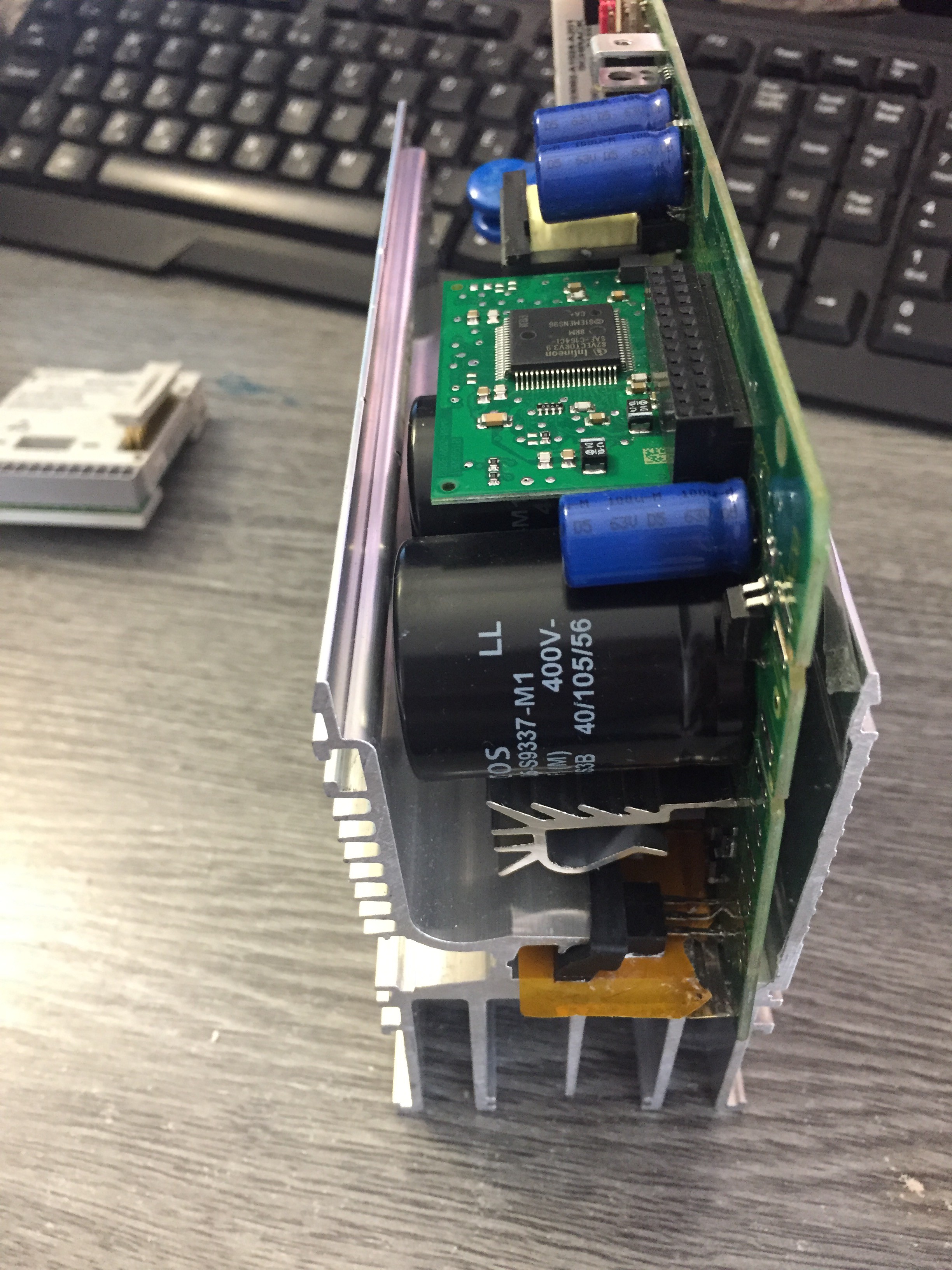
Now you can see it is not an easy assembly, because you have to bend the left side of the metal to get free those IGBTs and Diodes. If you bend it a little bit, you can push the circuit board out the metal heatsink/ case.
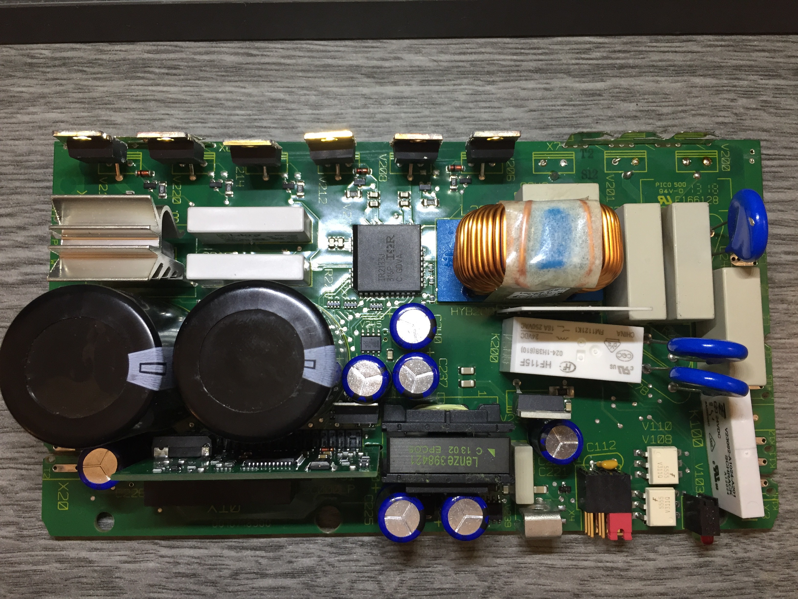
You can see here I already disoldered the three diode and I left the six IGBT in place (left side top).
In the middle you can see a big IC, which is an integrated 3 phase IGBT driver. (IR2133J)
At the middle bottom there is the transformer and next to it left the processor board vertically.
Lets see those rectifier diodes:
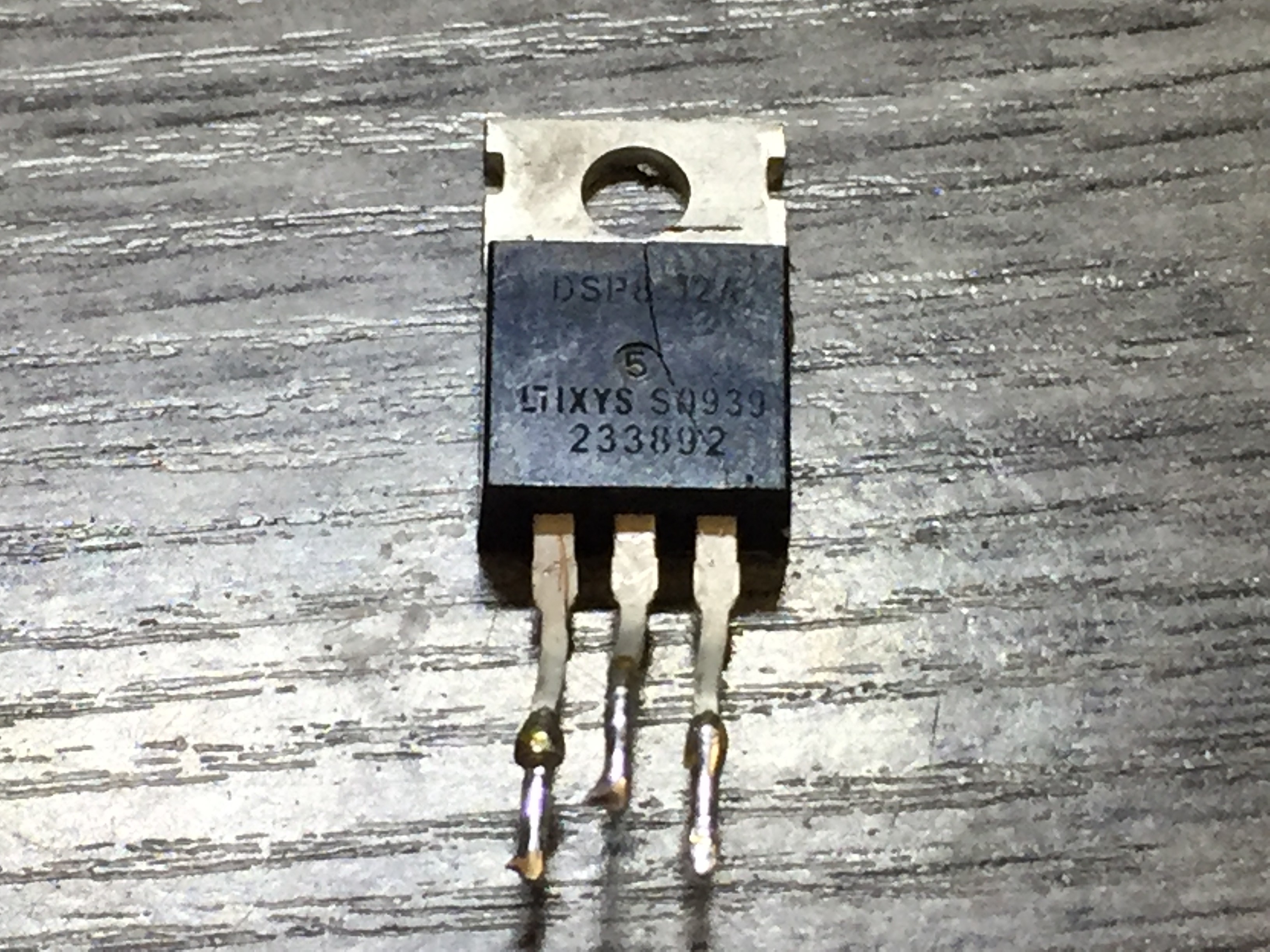
One of the three locked like this, it cracked half, so it was obvious it is bad with an other on as well, which was not cracked, but that was short.
I orderred three new one, because if one dies, useally an other get damage as well, so it is recomended to change all at the same time.
I changet it and assembled the drive and tested it with one phase. I put series with the drive an 100W light bulb, so if it changed there mind of the state of fixed, I shoud be safe, because the light bulb must limit the current so it would not blew up with that much energy.
I had a success with the repair, I tested the drive and it worked perfectly.
Discussions
Become a Hackaday.io Member
Create an account to leave a comment. Already have an account? Log In.
Hi I am having a problem with one of the electronic components of lenze vfd. It is a 3 leg transistor mounted close to transformer. Do you have any list of data's for that component? Thanks
Are you sure? yes | no
Hello. I want to troubleshoot my 9400 Lenze Servo driver. Where can i get schematic diagram or circuit drawing?
Are you sure? yes | no