 Jac Goudsmit
As I noted in the previous log, S/PDIF is way too much to handle for one cog of a Propeller. That's okay, I have 7 more cogs. But in projects like this where you have to divide the work over several different cogs, it's difficult to keep your head around things. At the time that I'm typing this, the plan is somewhat as follows:
- Unfortunately, some external circuitry is unavoidable. In the previous log I said I would like to get rid of it, but that's just impossible. The external circuitry converts the S/PDIF bi-phase signal of any polarity to a simple signal where each transition of the input is converted to a pulse. Then it's just a matter of timing the distances between those pulses to get the original binary stream.
- One cog (let's call it the "sync cog") will be in charge of recovering the clock signal from the input, and will put that signal on a helper pin that can be used by other cogs for synchronization.
- The same "sync cog" will also detect preambles and will generate output on another pin to synchronize the other cogs.
- A "data cog" will use the output signals from the first cog to synchronize to the clock and read input bits. At the end of a subframe, it will store the 32-bit decoded word in the hub.
- If I can't make the "data cog" fast enough to store data into the hub at the end of each subframe, there will be two "data cogs", one that reads the left subframe and one that reads the right subframe.
- Once the data is in the hub, the subchannels can be demultiplexed and dumped to the serial port or to the screen. It will probably also be possible to use existing open-source modules to send the code out to a recorder or a playback device, after optionally modifying the data.
I already noted that it was going to be necessary to mess around with the timers in the Propeller. Timers in the Propeller are incredibly useful -- as long as you just want to use them for output. For input tasks such as measuring time in a high-speed environment, the timers need a lot of help from the code:
- You can't let the code wait for a timer (only for the system counter and it takes three assembly instructions to set that up, and that's two too many for our purposes)
- There are timer modes that automatically start a timer when e.g. an input pin is low or high, to measure how long a timer input has been in that state. Unfortunately, the code still has to babysit the timer: if you're measuring how long a signal is high or low, the only way to tell that the signal is no longer in that state is to test it with assembly instructions (either by testing the signal directly or by testing if the timer is counting; both of which are several instructions that I don't have time for in this project)
- There are 2 timers per cog which is really useful (16 timers total is not too shabby), but that means that one cog doesn't have direct access to a timer's state in another cog. So to synchronize one cog with the timer of another cog, you have to sacrifice a pin and use it for output on one cog and input on another cog.
- There are some "logic" modes which allow you to analyze two input pins in various ways, but unfortunately it's not possible to generate direct output from these modes: the code has to examine the timer registers to see if anything has been registered. Nice for slow events but unusable for our purposes.
- The timer modes that let you measure the time that an input pin was low or high, allow you to provide an output pin but the output is always just a delayed version of the input, and the delay is always simply the input pin delayed by one clock cycle.
- There are various timer modes that generate useful output, especially the NCO and DUTY modes which use bit 31 of the counter, or the carry flag of an adder to generate output. This can be used to generate a pulse of a predefined length or after a predefined delay.
When I started on the project, I had set up a simple circuit with a 74HC04 and some passive parts to amplify the input signal to the full range of CMOS, and to generate a slightly delayed version of that signal that could be used to detect flanks, regardless of the polarity of the original signal. With a WAITPEQ or WAITPNE instruction, it's easy to detect whether pins are equal or different (just test both pins at the same time and use the Carry flag to detect the odd parity). As I already mentioned in the previous log, that wasn't going to be fast enough by a long shot.
With timers, it's not possible to use two input pins at the same time. So I added a 74HC00 to my breadboard to make an XOR port, so I would have a low latency signal that indicated whether a flank (upgoing or downgoing) had been detected in the input signal. The signal on my breadboard is now roughly as follows:
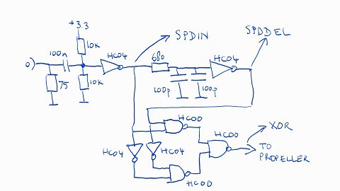
I combined the two delay ports into one by putting the two 100pF capacitors in parallel. Of course now there's only one inverter between the first stage (called SPDIN for SPDIF IN in this picture) and the second stage (called SPDDEL for SPDIF DELAYED) so the polarity of the delayed signal is now reversed compared to the schematic in the previous log.
The three NAND ports that I added and the two NOT-gates generate an output that's HIGH when the SPDIN and SPDDEL signals are the same, which happens for a short time when the input changes polarity (remember there's an inverter so the delayed signal is different as long as the input doesn't change). By the way, it looks like I may not need the NAND ports after all. I'll regard that as an optimization so I won't worry about it for now.
I decided to send in the big guns and dig out my HP 16500C logic analyzer / oscilloscope (see the photo near the top of the log) from the garage, so I could play around with this. I bought it from eBay a few years ago and I don't use it often because I don't really have space for it. When I got it, it was noisy too, but I replaced the hard disk by a 64MB CF card and replaced the two loud fans with a single quiet one that still moves plenty of air to keep the system cool.
Having an oscilloscope and a logic analyzer allowed me to quickly try out a bunch of different approaches to recover the clock from the input (and generate a signal that I can hopefully use in a future "data cog" to read the data.
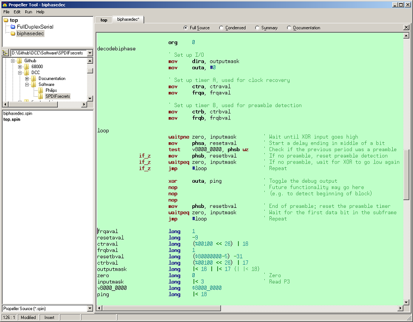
This piece of code sets up two timers, both in NCO (Numerical Controlled Oscillator) mode. It then strategically resets the timers when certain things happen.
- At the beginning of the loop, the program assumes that the P3 input (the XOR output of the circuit diagram above) is LOW.
- It waits until the pin goes HIGH, indicating that the input changed.
- Then it resets timer A which generates a pulse that is exactly the right size to end at the time when (during a bit with value 1) a second pulse comes in on XOR.
- Then it tests whether the time since the previous change in the SPDIF is long enough to indicate the start of a Preamble (all preambles start with a 3 biphase bit absence of changes in the SPDIF signal). The Z flag is cleared if a preamble was detected, or set if it wasn't.
- If this wasn't a preamble, clear the preamble timer (i.e. start measuring from now), wait for the end of the pulse on the XOR line if necessary, and the repeat the loop to wait for the next pulse.
- If this was a preamble, keep busy for a while, then do the same things that a non-preamble loop would do and repeat.
Obviously this could use some cleanup but the result can be seen in the photo of the logic analyzer screen: the code correctly generates clock pulses and a longer pulse indicating that a preamble was encountered.
I wrote some code to test whether another cog could successfully read the data by waiting for the recovered clock to go low and then sampling the XOR pin, but this didn't work. First of all, it took too many instructions (basically it can't get its work done on time). Second, there is not enough time to wait for the clock and then read the data: by the time the data-reading instruction is being executed, the input is gone.
In the next log I'll try to fix this by doing two things:
- First, I'm going to change the code so that the recovered clock runs at half speed. That way, the data cog(s) only has/have to wait for the next state with WAITPEQ/WAITPNE; they don't have to wait for the end of that state.
- Also, I'll have to change the timing so that it's possible to either do a WAITPEQ/WAITPNE that waits for the clock and also checks the data, or I'll have to change the timing of the sync cog to allow for sufficient delay in the data cog to pick up the data at the right time. This might be difficult: I have a funny feeling that the sync cog may not have enough time to do this.
Discussions
Become a Hackaday.io Member
Create an account to leave a comment. Already have an account? Log In.