 Jac Goudsmit
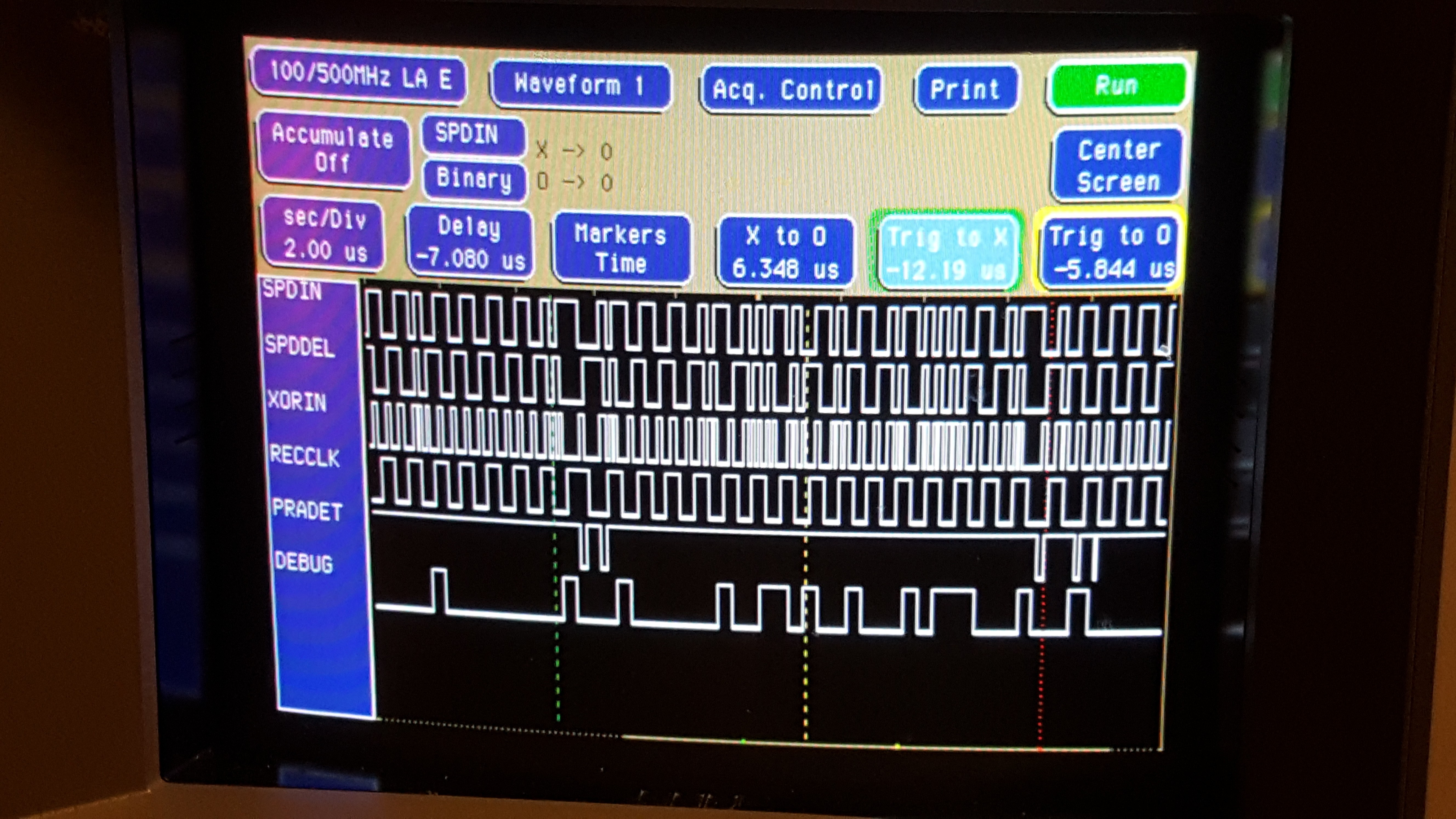
A quick update:
I rewrote the code that regenerates the clock from the incoming SPDIF signal, and as you can see in the picture above (next to the RECCLK label), it's very steady now, and it runs at half the bit rate. So instead of generating one clock pulse (i.e. an up/down cycle) for each input bit, the RECCLK signal only changes once for each input bit.
That means that the code in the data sampling cog(s) has to be repeated twice: first it waits for RECCLK to go high, then it reads a bit, then it waits for RECCLK to go low and reads another bit. This may look a bit sloppy but is not uncommon in Assembly programming: it's basically a partially unrolled loop. I may go one step further and unroll the entire loop for a single subframe (so the same code will be in the source file 32 times), if there's not enough time to get things done.
The code uses a constant to delay the RECCLK signal by a variable number of clock cycles (it uses a timer in NCO mode). Basically:
- The sync cog waits for the XORIN input (the "original" SPDIF xor'ed with the delayed SPDIF to detect flanks) to go high
- It then starts a timer to toggle the RECCLK output
- Then it waits until the output is actually toggled and starts the timer to toggle the RECCLK output again
- After this, things start over from the top.
I also added preamble detection code which correctly identifies preambles (see the PRADET trace) but needs a little work: I want to make it generate a single pulse that starts right when the first long input pulse is detected, and ends when the first bit of the next subframe comes in, but as you can see, it triggers multiple times. For now it's good enough to trigger my Logic Analyzer so I can record an entire subframe.
I also implemented a small "debug monitor" cog that puts the data bits on a pin that's shown here as "DEBUG". As I mentioned in the previous log, the idea was to synchronize the data cogs on the recovered clock, and sample the XORIN pin at the time when RECCLK changes state. But this is actually a bad idea: The delay circuitry is very simple and there's a lot of jitter: I've seen recovered clock cycles that were more than 50ns too long or too short because of the jitter on the delay. That makes it pretty much impossible to get the timing right if I want to sample the signal right at the time when a second pulse comes in over XORIN.
But the Propeller timers can be programmed to count negative or positive edges, so that the exact delay time in the external circuitry becomes a lot less critical. The Debug Monitor cog that I programmed, basically waits for the RECCLK signal to change, and then checks if the Propeller timer detected two negative edges in the last cycle. If so, it sets the DEBUG output to 1, otherwise it sets it to 0. As you can see, it correctly decoded the subframe in the middle (between the PRADET pulses) as (1)0000'0010'0110'1001'0001'0111'0001(0) (the 1 at the start and the 0 at the end are false readings because of the preamble, I'll deal with those later).
What bothers me a bit though is that it was difficult to get the debug cog to work right: it's synchronized to the RECCLK with WAITPEQ/WAITPNE instructions but when I simply had the code read the data after each WAIT and then restart the timer, I couldn't get reliable results no matter how I set the delay for the sync cog. I had to basically:
- Wait for the recovered clock RECCLK using WAITPEQ/WAITPNE
- Wait for a little while longer using NOP
- Check if there were 2 negative edges of XORIN
- Reset the edge counter
- Wait for the next edge of RECCLK.
It bothers me that this way, the timing is partially based on the time it takes to execute the instructions. It means I'm doing something wrong or I need to use another timer in the debug cog (which may later become the data cog).
I'll have to take a thorough look at the debug cog and analyze what's going on and where the delays are. For one thing, the timer that detects negative edges is delayed by one clock cycle.
Another thing is that if I need to start the edge-counter at a different time compared to the RECCLK signal, it may be easier to just wait for a positive-going XORIN pulse instead of going through so much trouble to regenerate the clock and synchronize it with the time that an extra pulse would come in.
In short: it looks like it works but this needs some more analysis.
Discussions
Become a Hackaday.io Member
Create an account to leave a comment. Already have an account? Log In.