 Stephen Holdaway
Prototyping in advance
My brother lives in a different city, so before I had access to the problem hardware, I made a few guesses at home about the hardware, and wrote some firmware for the ATTiny13A against a mock-up on a breadboard:

Target hardware
When I was visiting a few weeks later with access to the lights, I refined the software and hardware against the real target. Unfortunately I didn't take many photos during this process, but it was fairly straight forward:
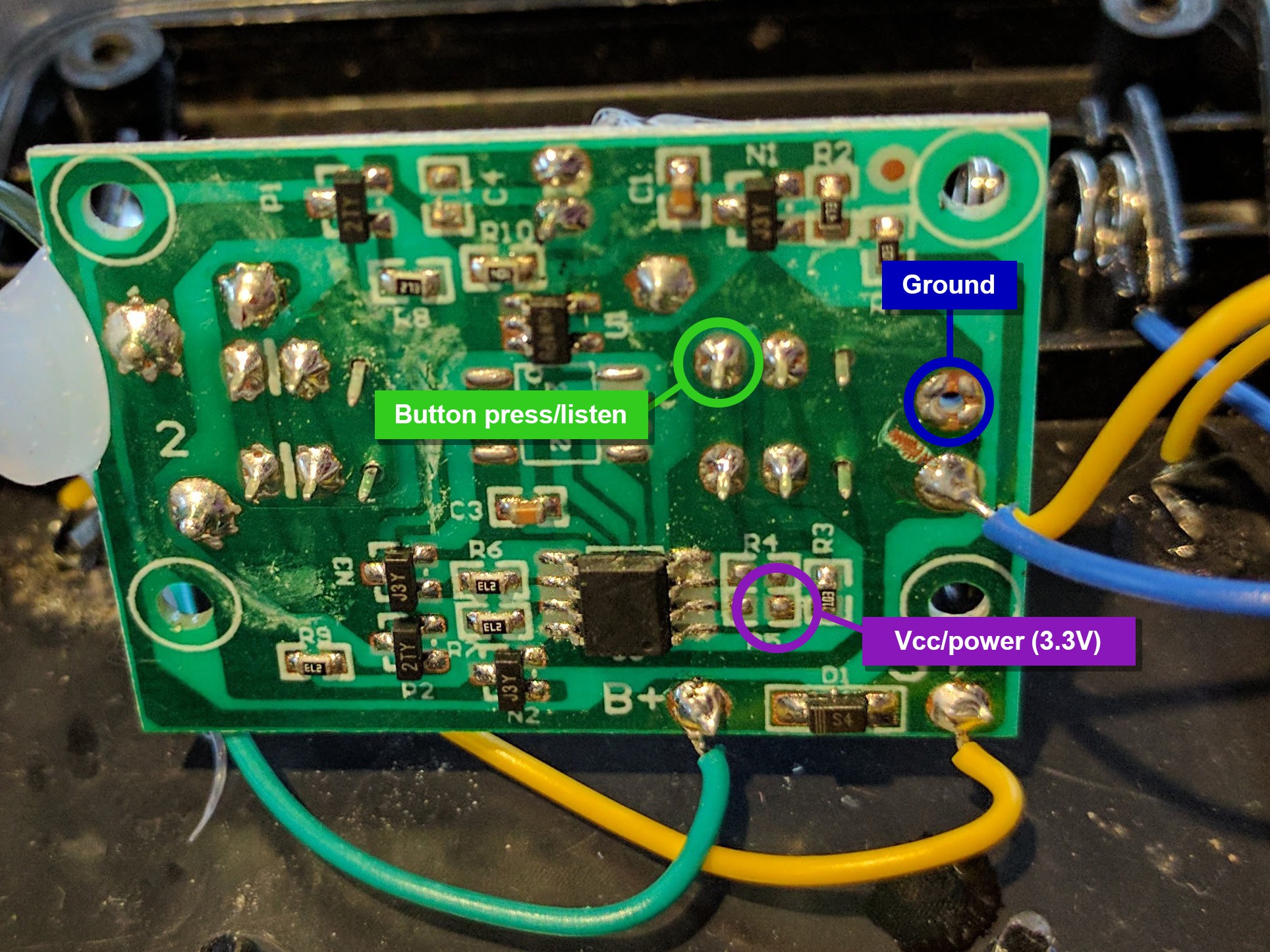
- Looked for a power and ground line that could power the ATTiny13A
Success - the NiMH battery on-board is stepped up to 3.3V for the existing MCU and lights. - Used a multimeter to check if the button was active high or active low
This one uses active low, which is understandable since it avoids an extra resistor and this is an ultra low cost product. - Poked around further for kicks with a logic analyser to figure out how the light patterns were achieved with two wires (didn't have an oscilloscope accessible)
The lights are wired in parallel with alternating polarity. Applying voltage across the two wires lights half the lights (every second LED), and applying the opposite polarity lights the other half. Neat.
The firmware I'd written at home worked great after a few timing tweaks, but the number of external components required seemed like it could be improved.
In the interest of easily wiring a loose ATTiny13 chip in by hand, I made some firmware adjustments that got the components down to a single resistor on the press line to limit current when simulating a press (as this is otherwise connecting Vcc directly to ground):
After hacking in a loose ATTiny with some thin wires and through-hole resistors, it was working great. I don't have a photo of this hacked in chip, but it was pretty janky, so maybe that's for the best...
Here's a video with it moving automatically to mode 7 of 8 when powering on:
Unfortunately the target board doesn't accept button presses for half a second after start-up (even though the lights come on immediately), so it's not an instant restoration of state.
Putting it on a PCB
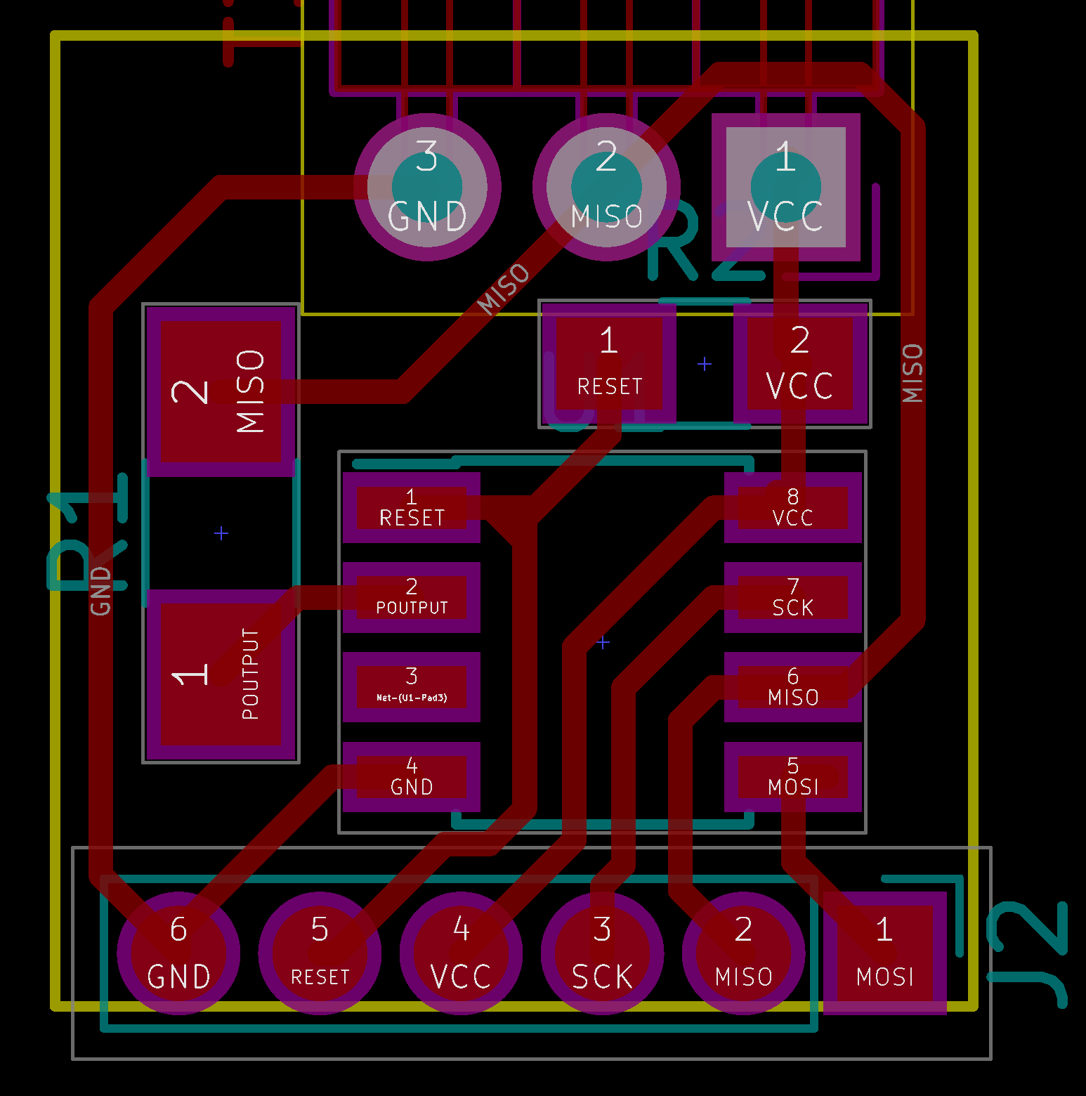
With confirmation the idea worked, and refined firmware and circuit, I set out to make a couple of PCBs to send my brother when I got home:
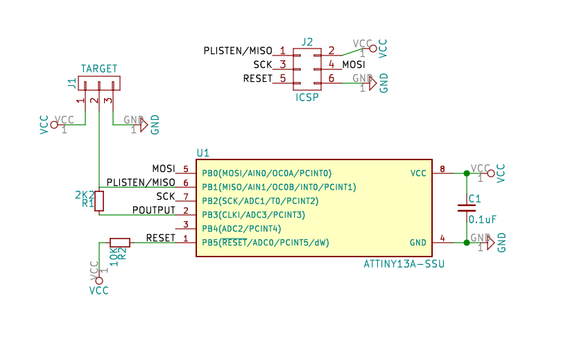
To make the circuit board work single-sided, I dropped the decoupling capacitor from the schematic, and rearranged the programming header. The prototype didn't have a decoupling cap either, and this didn't appear to cause any problems for this hack job.
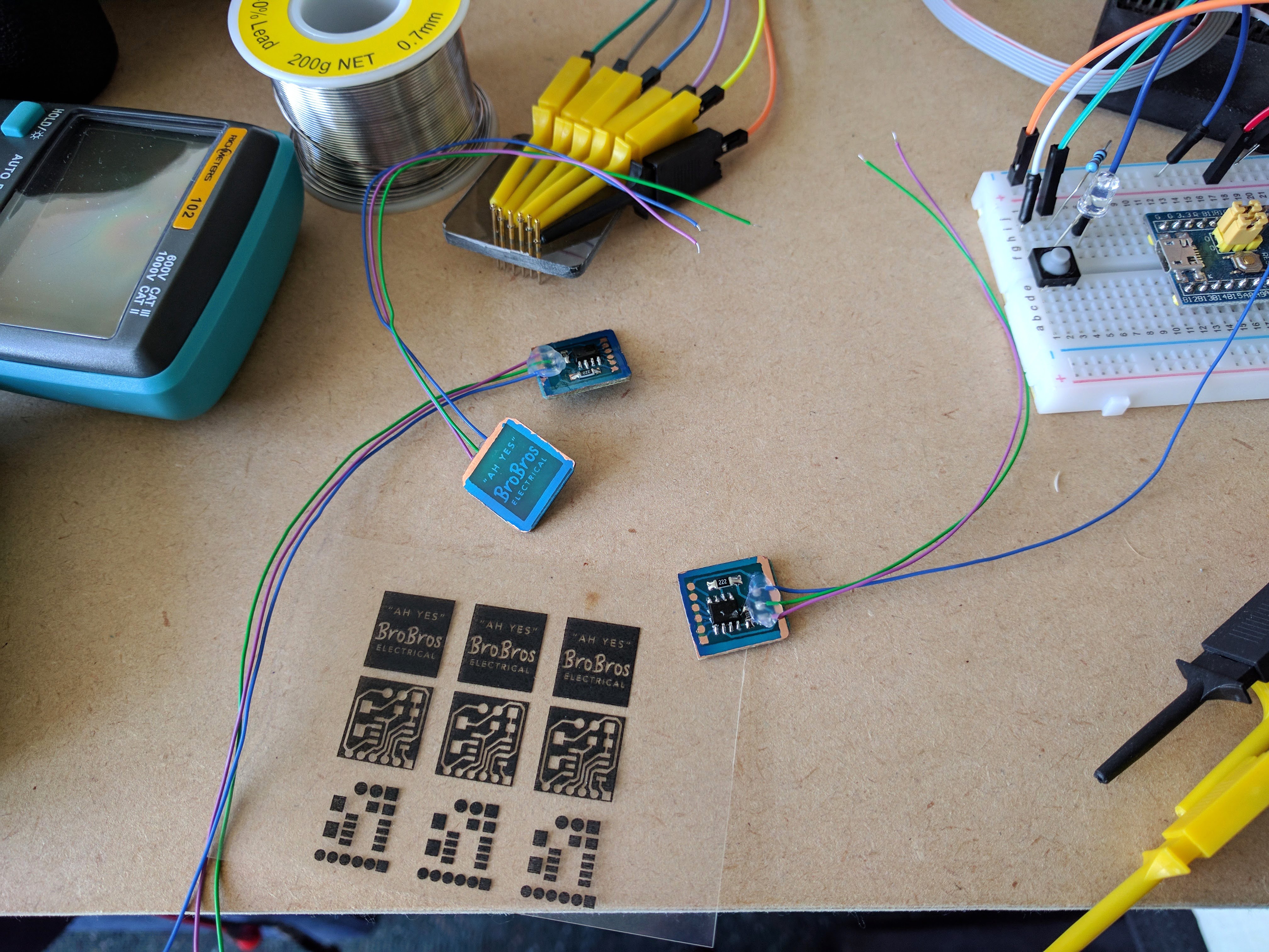
After programming with a hacked together pogo-pin rig, testing each item, and securing the wires and spraying with a weather-proofing clear-coat, the result was pretty sweet for half a day of work:

 JP Gleyzes
 Christian
 Bob Baddeley
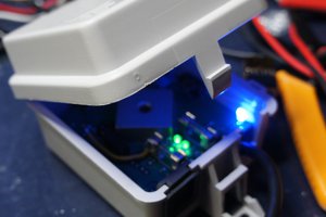
 KingOfKYA(Travis K. )