 W5VO
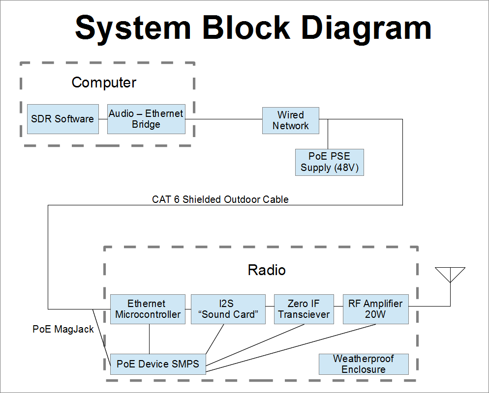
W5VOBasically, this is a "headless" radio designed to be computer controlled. We get a lot of value out of an Ethernet cable, as it carries the baseband signal, power, and control. Below is the system block diagram:
Stop wasting time and money on expensive coaxial cable and put the whole radio right at the antenna feedpoint!
Already have an account? Log in.
To make the experience fit your profile, pick a username and tell us what interests you.
Basically, this is a "headless" radio designed to be computer controlled. We get a lot of value out of an Ethernet cable, as it carries the baseband signal, power, and control. Below is the system block diagram:
So my initial plan (when I was shopping for microcontrollers) was to use the internal ADC and DAC of the microcontroller for feeding and reading the radio. However, it slipped my attention that there were a lot of qualities present in an audio-grade sampled setup that are different from just a simple ADC or DAC on a microcontroller. First, the sample rates for the ADC and DAC can be as high as 192kHz, which was really pushing it for the on-chip DAC. Second, audio signals are recorded and reproduced with higher resolution. While that doesn't mean that you get all of the added resolution, you definitely get more, and when the ADC is part of the detection chain.....
At any rate, this basically adds another layer of complexity to the design as a separate ADC and DAC chip is required. These ICs are typically called CODECs, and they operate using a protocol called I2S (Inter-IC Sound). Essentially this looks like SPI, but with some alternate signalling between words. Fortunately the ST32F407 has an I2S mode on two of the SPI peripherals, meaning that I can still use that chip for development. Other chips in the F4 series have actual "sound interfaces", so I'm not sure yet if I'm getting away with something or shooting myself in the foot. I'll assume the best and we'll see what the result is.
I found selecting a CODEC to be fairly difficult. I wanted:
There isn't a really easy way to do a comparison that I found to evaluate individual offerings, and the distributors (Digikey and Mouser) were less help than usual. To add to the confusion, the ADC and DAC can have different max sample rates, and only the highest is reported. Right now I'm leaning towards the Cirrus Logic CS4270
While the ST32F407 claims Ethernet connectivity, it doesn't actually have the Ethernet transceivers needed to talk directly to a piece of network cable. This interface, commonly referred to as a PHY, is left to the user to implement. It appears that Ethernet PHYs have a few standard interfaces: Media Independent Interface (MII), and Reduced Media Independent Interface (RMII). A few key differences between MII and RMII include a reduced pin count for RMII, and the data clock rate is 50MHz for RMII while only 25MHz for MII. While I don't feel like I'm in a crunch for pins, the RMII I/O looks better due to fewer apparent edge cases that the MII interface supports. Browsing through available Ethernet PHYs, it appears that Microchip makes the least expensive versions, and the cheapest one (LAN8720A) only supports RMII. Since my research has shown a slight preference to the RMII configuration, I have chosen the LAN8720A to be the Ethernet PHY IC.
Another thing to keep in mind when heading towards an Ethernet-based device is that the selection of the jack is important. Looking for something straightforward, it's easiest to use jacks with integrated magnetics. This means that there are transformers inside the jack for each TX and RX pair used. The transformer windings for Power over Ethernet (PoE) are also different, as the cable side requires a center tap for accessing the DC power without disturbing the signal. There are a whole lot of flavors of jacks and PoE varieties, but ones rated for PoE+ should tolerate the highest amount of current.
Both the jack and PHY will be integrated into a daughterboard for the STM32F4 Discovery development board.
I had a few goals when choosing a microcontroller. I wanted a built-in Ethernet interface, USB, plenty of serial IO, ADCs and DACs. Also important was the availibility of an inexpensive development board and an unrestricted (ideally open source) build platform. From basic searching, I came up with the STM32F4 Discovery board based on the STM32F407. The '407 is available in a few friendly TQFP packages, so it will be relatively easy to create a new board using it when the time comes.
The Discovery board is really well equipped. A large majority of pins are routed out to the pin headers. For now, the main concern is being able to find enough unused pins that can map to the needed peripheral functions. Worst case scenario is that I have to start desoldering parts, but hopefully it won't come to that. The first thing to do will be to develop a daughterboard with all the needed digital functions and interfaces needed for the radio.
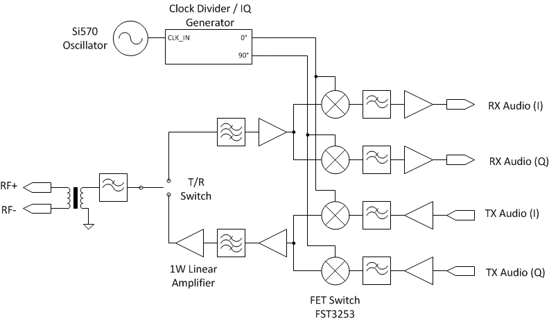
The radio topology that I have centered on is a direct conversion I-Q receiver seen in many HF software defined radios. The goal at this point isn't to build for high performance, but for functionality, low cost, and ease of design. While the fundamental core is not designed to work at a specific frequency, the filters must be designed around at least the expected band of operation. In multi-band radios, filters are switched in and out based on the frequency of operation, but this adds a lot of complexity. While I don't think avoiding multi-band operation requires a ton of justification, a good reason is that the targeted use case is a mono-band dipole antenna on 20m. With the radio effectively part of the antenna, it wouldn't be necessary to pack multiple band operation when it wouldn't be used.
The baseband inputs and outputs are designed to be by a sound card, resulting in a transmit and receive bandwidth limitation of 50-75kHz. The mixer is repurposing a digital bus-mux switch. The oscillator will be a Silicon Labs Si570 oscillator, which will give a lot of flexibility to a prototype system. A future version might use a simple crystal oscillator as the Si570 is definitely not a budget part. The oscillator operates at twice the center frequency, and the I-Q signal generator creates the quadrature spaced signals required by the mixer.
The RF filters are primarily focused on reducing the second and third harmonic of the radio. FCC regulations require spurious signals to be at least 43dB below the fundamental signal. In order to meet this target, the band-pass filters and the output filter will be designed to have at least 43dB suppression of all harmonics. Proper phasing operation will be critical to achieving the close-in response, as there isn't really an easy way to tackle that.
One other goal is to minimize the number of hand-wound magnetics, as that always ends up being a deterrent to me to get started. Reducing the reliance on these parts also helps improve the manufacturability of the radio.

I have thought for years that because of Ethernet, the Tx section needs to be outside with a direct ground point, with direct connection to antennas, with or without the Rx section...and isolated via Ethernet (isolated by fiber via media converters) to keep the lightning strike outside, controlled inside over Ethernet per your model. Thank You for thinking past the old dynamic; maybe the manufactures will finally wake up based on your work here/AG8R

Hi W5VO, Have you been successful in implementing ethernet with STM32.
Can you please share your experience...
 lion mclionhead

 rodrimen
I've been trying hard to get CS4270 to work but without any luck. Can you share any further information?