 Bud Bennett
[Edit 2019-11-15: This is becoming the never-ending project. I have been prodded by several people that want to extend the design to work with a stack of supercapacitors. I had no need for that, so I did not put any effort to insure the functionality of a stack, other than allowing for it by programming some component values on the PCB. But since the capability is there it should function correctly. I'll be trying to implement the dual supercapacitor functionality over the next few days/weeks.]
I have 3 Raspberry Pi computers running 24/7 in headless mode scattered around my residence. One of them is an old Pi1B that manages my heating system and monitors my water well. I consider it a mission critical piece of hardware. Invariably, when I leave for a trip in the winter the power will fail, so I need a means to automagically and gracefully shutdown all of the headless Pi’s.
I built a working UPS using a stack of two 400F supercapacitors about three years ago: https://www.raspberrypi.org/forums/viewtopic.php?f=37&t=50470&hilit=controlled+shutdown&start=25. It was a relatively simple solution that did not make very efficient use of the supercaps, but now with more power hungry versions of the Raspberry Pi I decided it was time to build a new one with higher load capacity (and re-purpose the supercaps).
The energy that you can get from a capacitor is simply
where V1 is the initial voltage across the capacitor and V2 is the final voltage across the capacitor. The output energy is in Joules (Watt-seconds). It is evident from this equation that you can get much more energy out of the capacitor if you can get a lot of voltage across it and take more voltage from it. The problem is that affordable supercaps don’t exist with voltage ratings above 3V (typically 2.7VDC).
So just stack them like batteries then. What’s the big deal? When you stack two identical capacitors in series you get half the capacitance value. This is actually not as bad as it sounds since your energy capacity goes up with the square of the applied voltage. So if we had a stack of 4 supercaps that we could put 10V across would produce 4X more energy than a single supercap with 2.5V across it. Or conversely, you could use smaller supercaps to get the same energy output. The basic problem with this thinking is that the prices of supercaps don’t scale linearly with size — a 400F is $12 while a 100F is $8-$12, so 4 of them will cost a lot more. Another issue with stacked supercaps is one of balancing. The capacitor voltages need to be kept in balance to avoid exceeding the rated voltage. This requires extra circuitry, cost and complexity in the charging circuitry.
My heating system only needs backup power long enough to shutdown the system — a last gasp.
The current design:
Analog Devices recently (as of 2018-10-1) released the LTC4041, a supercapacitor backup IC. It takes care of the charging of the supercapacitor and the balancing, if there are two of them. It also manages the switchover from powering the load from an AC source to powering the load from the supercapacitor backup. What it doesn't manage is the timers required for the interval when the Raspberry Pi is committed to shutting down and the power-off interval which resets the Raspberry Pi and allows it to reboot when AC power becomes available again. This is the required functionality of the design:
- Provide 5V±0.25V power to the RPi @ 500mA to 2A max.
- If the power fails, continue to provide 5V from a single (or dual) SuperCap charged to 2.7V (or 5V). And indicate the power failure to the RPi.
- Backup power must be provided for a minimum of 35 seconds. The current load will be high until the RPi shuts down into a low current state that only draws about 50-80mA. It takes about 10-20 seconds to enter the shutdown state.
- The RPi will assert a SHUTDN input to indicate to the UPS that it has committed to the shutdown sequence. The UPS must provide backup power for 15-20 seconds after the SHUTDN input is asserted. The UPS must also disconnect the power input from the load after this interval to prevent the RPi from hanging in shutdown mode if the input power is reapplied.
- At the end of the shutdown interval the power is disconnected from the load for at least 5-10 seconds to allow the RPi to reboot when power becomes available again. If power has returned during the shutdown interval it is reapplied after the disconnect interval.
- I would like to keep a fair bit of voltage on the supercap at the end of this cycle. Sometimes the power glitches on/off at short intervals so there should be a reserve on SCAP to handle a few of those events.
This is the latest schematic, which should work for a single or dual supercapacitor implementation:
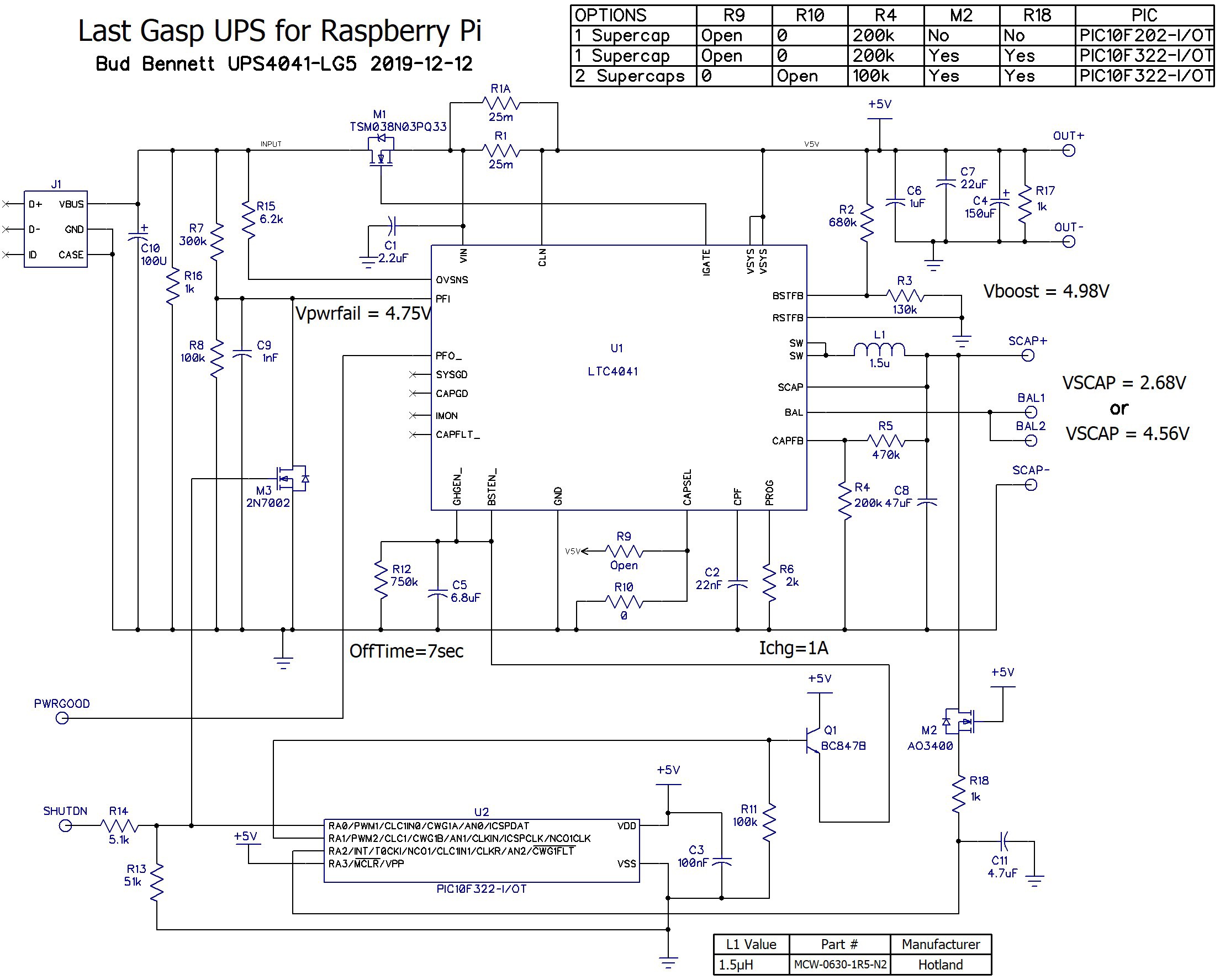
There is quite a bit more functionality than the original discrete design, while lowering the component count drastically. The LTC4041 automatically charges the supercaps with a programmable current. If the total current drawn from the input source exceeds a predetermined threshold then the supercap charging current is reduced to avoid overloading the current capabilities of the input source. When the input power fails the LTC4041 detects the failure and automatically switches from using input power to drawing power from the supercap via a switch-mode boost converter -- up to a maximum 2.5A load current at the output (2 supercaps required to get 2.5A).
What the LTC4041 doesn't do is timeout the interval that the Raspberry Pi needs to safely shutdown to avoid corrupting the SD card which contains its operating system. I've provided some additional circuitry to manage that task.
When the input power fails the PWRGOOD signal is pulled low by the LTC4041 to make the Raspberry Pi aware that there is a power failure, and it switches over to providing power from the charge stored on the supercapacitor. If the power is not restored before a period of time determined by the Raspberry Pi then the Raspberry Pi asserts the SHUTDN pin. A one-shot is then triggered, which keeps power applied to the Pi for about 20 seconds, allowing the Pi to terminate running processes and enter a shutdown state. At the end of the one-shot interval the power is removed from the Pi for at least 5 seconds. If input power becomes available again during this shutdown interval the power is not made available to the Pi until after the power is removed for that 5 second interval -- this prevents the Pi from hanging in a perpetual shutdown state.
The LTC4041 is disabled by pulling the GHGEN_ and BSTEN_ pins above 1.4V at the end of the shutdown interval. There is an RC timer on those pins that won't re-enable the backup boost converter for at least 5 seconds. When the voltage on those pins drops below 1.4V, the LTC4041 won't enable the boost converter if the voltage on the SCAP pin and the voltage at OUT+ is below 2.5V. The PIC10F322 monitors the voltage at SCAP and won't assert the RA1 pin until the voltage at SCAP is less than 2.5V. This ensures that the booster will remain disabled until input power is reapplied.
The circuit waits in a standby mode until input voltage increases above 4.8V and the input switch reconnects the input source to the Raspberry Pi, allowing it to reboot, and also begins the process of recharging the supercapacitor(s).
There are essentially three configuration options now. A PIC10F202 can be used for a single supercap solution, but R18 and M2 must be depopulated. Otherwise the PIC10F322 should be used with both R18 and M2, and R9, R10 and R4 set to the correct values for either 1 or 2 supercaps.
The Old (Original) Design:
The following is a description of the original circuit, which employed a lot of discrete devices since there really wasn't an alternative.

It’s a lot of parts, isn’t it. When things have to work at low voltages there aren’t a lot of options.
Design considerations:
- I was shooting for a UPS that could output 2.5A for ~30 seconds. This is 375 Watt-sec. A 400F supercap can deliver this amount of energy by giving up about 375mV. Since the boost converter is not 100% efficient I wanted the booster to operate down to 2.0V. There aren’t many choices at this voltage level. I used an LT3759 since it is specified to operate down to 1.6V, uses external FET switches, and has a clever gate drive circuit that benefits from the output voltage at 5V when it has to take over providing power. The LT3759 can run at frequencies up to 1MHz, which allows smaller inductors with higher current ratings. Even so, the inductor L1 and Schottky diode D1 are the largest components on the board. The peak inductor current is 3X to 4X the required load current, so you must get an inductor that can handle 7-10A. Same with the Schottky diode, which is a dual component in a DPAK rated at 7A (3.5A/leg). One last thing… there is a 1000uF capacitor at the output to hold up the output voltage while the LT3759 spins up to full current. Without this large capacitor the output droop when switching over to boost mode would probably cause the Pi to reset. This big surface mount capacitor is pricey — more than $2.
- The wall wart is 5VDC@2-2.5A. It is not quite standard issue in that it must provide 5.15-5.25V minimum. It is increasingly more common to find them in this voltage range since they need higher output voltage when providing 2-3A through a long length of pretty small gauge wire. The wall wart can be easily modified to provide slightly higher output voltage. I cut off the long lead and substitute a shorter lead with a larger gauge.
- About wall warts… Notice that there is no blocking diode for the wall wart input. A bit of sleuthing on the internet revealed that (almost) all of them use the same TL431-type output circuit that simply goes into a high impedance state when the AC input is removed. So the blocking diode, and its voltage drop, is not needed.
- I found my favorite FETs — the AO3400(NCH) and AO3401(PCH). These are sub-logic level FETs with 30V VDS, 5A ID, RDSon ~ 19-30mΩ, and gate drive is spec’d at 2.5V, in a small SOT23 package that can dissipate nearly 1W! All for $0.025/each. They can be paralleled to obtain even lower ON resistance, so I used them in two’s and three’s. Three AO3400’s in parallel have a total gate charge of only 18nC which is lower than most trench FETs with 11mΩ ON resistance @ VGS=4.5V. All of these specs mean cooler temperatures and faster switching.
- There are two timers. The LTC6993-1 provides a 20 second timer that times out the shutdown sequence. A 5 second timer is built into the input switch (R19-C7). It provides the interval where power is removed from the Pi in order to allow the Pi to reboot when power is reapplied.
- There are 2 GPIO interface signals between the UPS and the Pi. PWRGOOD is normally high but is pulled low by the UPS when the power has failed. The Pi monitors PWRGOOD for 10 seconds before it commits to a shutdown sequence. It then signals the UPS that it is shutting down by asserting the SHUTDN GPIO signal. The UPS then starts the 20 second timer before turning off power to the Pi. If power becomes available after the shutdown sequence is initiated the UPS will wait 5 seconds after removing power before making it available again to the Pi.
- The supercap is charged only when the booster is not operating. The charger is foldback current limited to keep power dissipation around 1W until the cap reaches 2.7V, then it just holds it at that voltage. I’ve measured the recharge time from a single power failure event on a Raspberry Pi 2B — it takes less than one minute to recharge the cap back to full voltage. To charge the 400F supercap from 0V to 2.7V takes 1.5 hrs.
So how does this thing work? Beautifully! Here’s a scope trace of the UPS holding up the output to a 2.5A load when input power is unplugged.

But I found that it is way over-designed. I expected my Raspberry Pi 2B to be quite a load, but a power fail event only takes the 400F supercap down by about 45mV, and that is with all 4 cores running 100%. That’s an average load current of less than 400mA (over 30 seconds). I tested a RPi3B as well and the supercap voltage dropped by about 55mV.