 Bud Bennett
I did not understand all of the implications of changing the PIC code to monitor the SCAP voltage. I was putting final touches on the new design when I started thinking about how it would work if the input power was applied while the UPS was in the delay period after the Raspberry Pi issued a SHUTDN command to the UPS. Since the PIC is now monitoring the SCAP voltage it will not shutdown the LTC4041 charger or booster if the input power is reapplied -- the LTC4041 will begin charging the supercapacitor and the SCAP voltage won't drop below the cutoff threshold. Therefore the RPi will just hang in a shutdown state as long as power is applied.
My solution was to add M3 to force the LTC4041 into a powerfail condition after the RPi asserts the SHUTDN input. This will prevent the supercap from charging and allow the UPS to complete its booster/discharge cycle before removing power to the RPi.
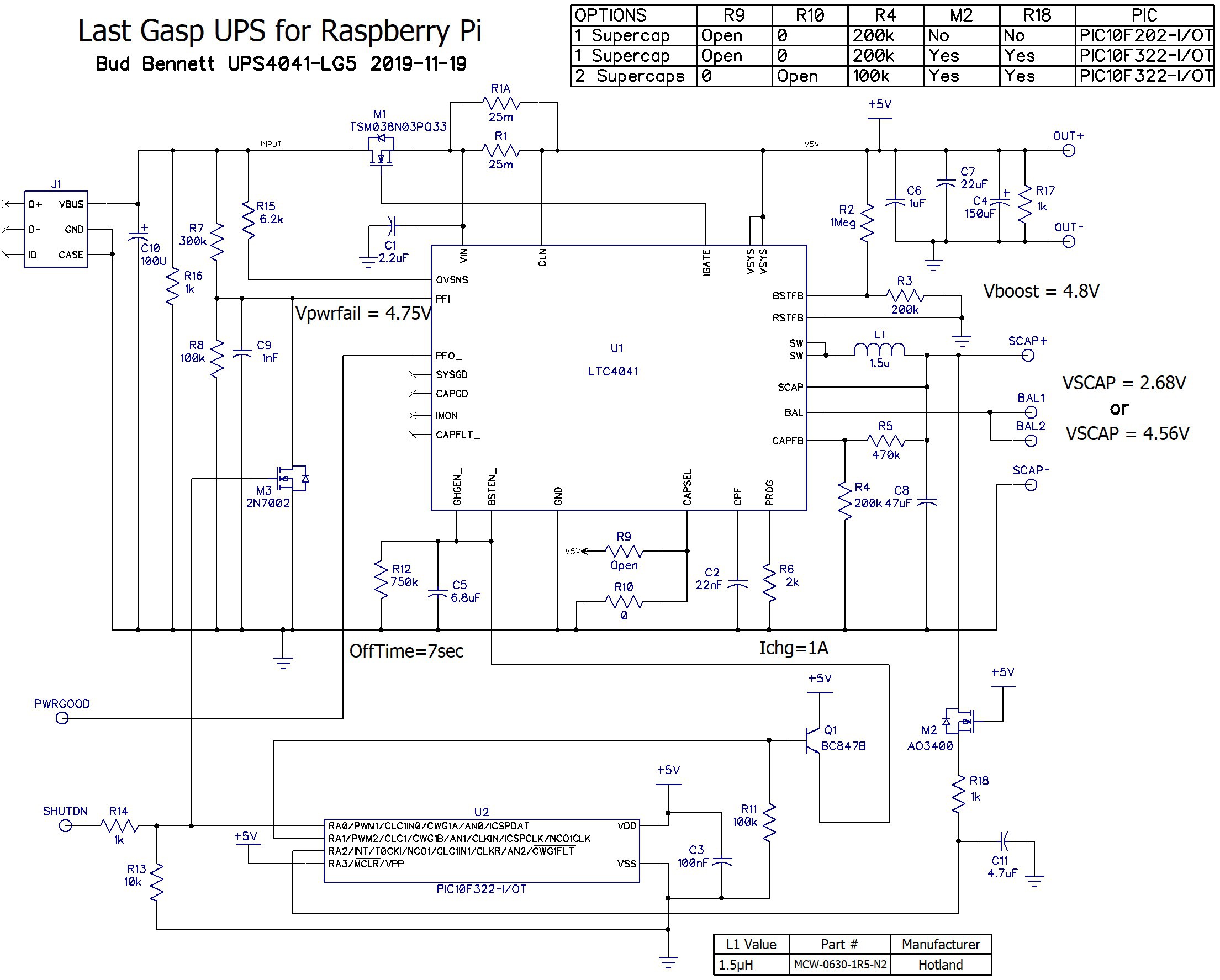
It is not a perfect solution. It might be subject to noise, but I'm hoping that the deglitching in the PIC will eliminate false hits. If M3 gets a short noise pulse it will cycle the UPS to provide power for a short time -- the RPi should ride through that without issues.
The addition of M3 to the PCB layout was easier than I expected.

Unfortunately, I will now get two PCBs from Osh Park...
More Consequences:
The addition of M3 only works if the RPi keeps the SHUTDN input high during and after its shutdown or poweroff. There are methods to force this in software, but I not a trusting guy when it comes to system software not changing over long periods.
I came up with a solution in firmware (it's not software, is it?) Since the gate of M3 is connected to the PIC RA0 pin I could change the pin to be an output and force VDD, 5V, on the gate of M3 after the PIC had committed to shutdown. The 1k series resistance, R14, would prevent the RPi from changing the voltage at RA0. It only takes two lines of assembler code:
bcf TRISA, 0 ; make RA0 an output
bsf PORTA, 0 ; latch RA0 high to keep LTC4041 in powerfail mode.
This is much simpler, and more robust over time, than messing with the GPIO settings during/after shutdown/poweroff. I will update the code in the files section. If it doesn't work for some reason I'll edit this log with an explanation.
Note: this might require a change to the values of R13 and R14 to prevent a latchup condition in the RPi when current is forced into the GPIO pin.
Breadboard Learning[2018-11-20]:
I decided that it might be instructive to take my only unused LG4 module and add the new components to see if there was anything else I might have missed. I had some TO92 2N7000 FETs in a box somewhere that could be used. I programmed a PIC10F322 SOT-23-6 package to replace the PIC10F202. I did not add C11, partly to see how good the noise immunity was and partly because it was difficult to add to the tenuous connection already tied to the PIC's AN2 input.
The first thing I did was reconfigure the UPS for two 100F supercaps and test for functionality. The SCAP voltage climbed slowly to 4.55V and stayed there. When I removed the input power the output voltage dropped from 5.1V to 4.84V, with a pretty light load of only 22Ω. The voltages on the supercaps was within 20mV during charging, so the balancing seems to work.
I then added all of the new components and applied 5.2V to the input, but this time I did not allow it to charge SCAP to 4.55V -- only to about 3V to keep the discharge time short with a 22Ω load. When I removed the input power the output again dropped to 4.84V and remained at that potential. The SCAP voltage dropped to 2.45V when the booster was disabled and the output voltage dropped to zero. I noticed that the SCAP voltage recovered to 2.55V after the load was removed, but the LTC4041 did not restart the booster after the 7 second disable period ended.
I performed several tests to see if there were any other unpredicted responses of the UPS to various stimulus. Most importantly, the UPS cycled properly when the input voltage was removed, the SHUTDN input activated, and then the input voltage re-applied before the 20 second one-shot period ended. This gives me hope that it will operate properly when a Raspberry Pi is used as a load.
More Breadboard Learning[2018-11-21]:
I was worried about the voltage recovery on SCAP after the load was removed, as evidence of the 100mV recovery when only a 22Ω load (220mA) was used. Today I connected a 4Ω load (1.21A) to the output, charged the 2-100F supercap stack all the way to 4.55V, and let it stay in steady state to cool down the LTC4041 a bit. I then disconnected the power and activated the SHUTDN pin shortly afterward. Here's what the voltages at OUT+ (CH1) and SCAP (CH2) looked like:
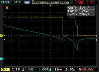
I triggered the scope just prior to removing power. The output is very steady until the booster is shutdown when the SCAP voltage touches 2.44V. The SCAP voltage immediately bounces back and climbs during the 10 second period when both CHGEN_ and BSTEN_ are above 1.4V. When CHGEN_ and BSTEN_ fall below 1.4V the voltage at SCAP has climbed to nearly 3V and the booster is turned back on for a short period until the SCAP and VSYS voltages fall below the max(SCAP,VSYS) under-voltage lockout of 2.5V. By that time the SCAP voltage has decreased below 2.5V and the booster is not re-enabled (at least not during the observed interval).
This may appear to be problematic, but I don't believe that it is. In a normal situation the Raspberry Pi will enter a low power shutdown or poweroff condition before the PIC instructs the UPS to disconnect the booster. Therefore, the snapback of VSCAP will be on the order of 100mV, instead of the 500mV exhibited by this test.
The VSCAP snapback can be managed further by using short leads on the supercaps (in this instance the leads were about 100mm long), and using supercapacitors with very low ESR. I bought these 100F supercaps from eBay, so I don't have any idea what their ESR specification is, but my perception is that it is not good. A short survey of 100F supercapacitors offered by Digikey shows a range of 8mΩ to 30mΩ. Get the 8mΩ stuff.
Discussions
Become a Hackaday.io Member
Create an account to leave a comment. Already have an account? Log In.