 V.G.C.
License: Open Source Licensing
0%
0%
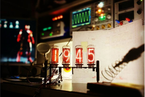
Nixie Clock on ESP8266 module
Nixie Clock on ESP8266 module with synchronization with NTP server. Simple circuit.
Become a Hackaday.io member
Already have an account? Log in.
Just one more thing
To make the experience fit your profile, pick a username and tell us what interests you.
Pick an awesome username
hackaday.io/
Your profile's URL: hackaday.io/username. Max 25 alphanumeric characters.
Pick a few interests
Projects that share your interests
People that share your interests


 c.forstner
 Muth
Muth
 Jan Waclawek
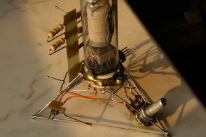
 DeepSOIC
How to get a detailed description with a diagram?