Close
0%
0%

Yapolamp

An experimental torch/flashlight intended to be safer for eyes, completely inspired by and built upon the TritiLED project

Similar projects worth following
Having followed Ted Yapo's TritiLED project, I'm using it as inspiration for a small torch for my children. Ted has been fantastic at coaching me in an area of electronics new to me, so he gets the project named after him.

Caveats about making this project or a derivative for children - be sensible. Nothing diminishes your responsibility to check this project or a derivative is safe for your applications and situations.

Primary aims:
1) A torch for the user to find their way around a dark room or for limited reading under a duvet.
2) Safer for the eyes than white or blue LEDs (if directly looking at the LEDs).
3) Turns itself off after a while to conserve battery, unless user resets the "on" period.
4) An "always on" glow/pulse/blink to allow the user to find it in the dark (without keeping everyone awake).

Secondary aims:
5) Long life between charges.
6) Easy and safe charging.
7) Learn about efficiently driving LED light sources.

WHY

I wanted to make this because my son is probably going to shine whatever torch he can find in his eyes and my understanding is that shorter wavelengths in the blue and UV region can damage your eyes if too much enters your eye. As I understand it, most white LEDs rely on a blue LED stimulating phospor which adds in the red/green or yellow frequencies to make us think the light is white. Secondly, blue light isn't going to help him get to sleep if he uses his torch under the duvet to read - not enough melatonin. Added to this is a desire to keep the occasional flash in my eyes at night from ruining any night vision I may have, so I've decided to explore longer wavelengths. In the UK, most streetlights have been sodium lamps (until white LEDs started to replace them) so orange-yellow is a familiar tone and we'll start with that. We can move on to green and perhaps the cyan LEDs used in TritiLED but I think yellow would be a nicer colour if we can only have one wavelength. The thought of combined wavelengths sounds attractive but I'm not keen on the complexity that various LED forward voltages and optimum efficiency currents would introduce.

CONTROL

We'll use a time limit to prevent the supercapacitors being run down if the user doesn't keep the device on. An ATtiny402 is used in V1.3 for it's lovely peripherals and the events system that knits them together.
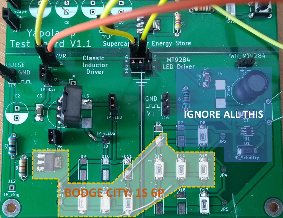
DRIVING LEDS

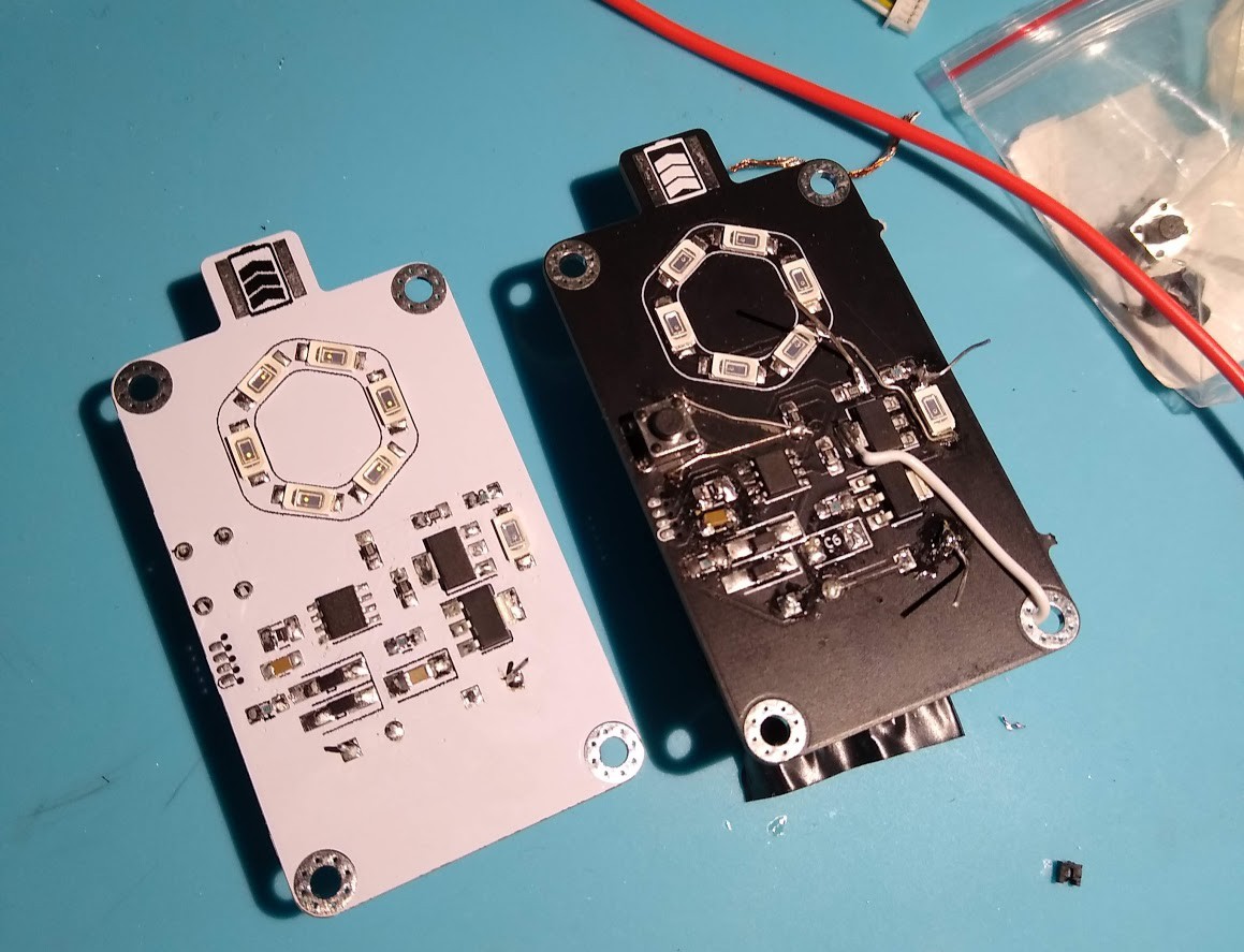
I've got a bit better at this since the Beta version, which was a Christmas present to my son two years ago. The logs hold the details of my journey in efficient LED driving.

"BATTERY" LIFE & CHARGING

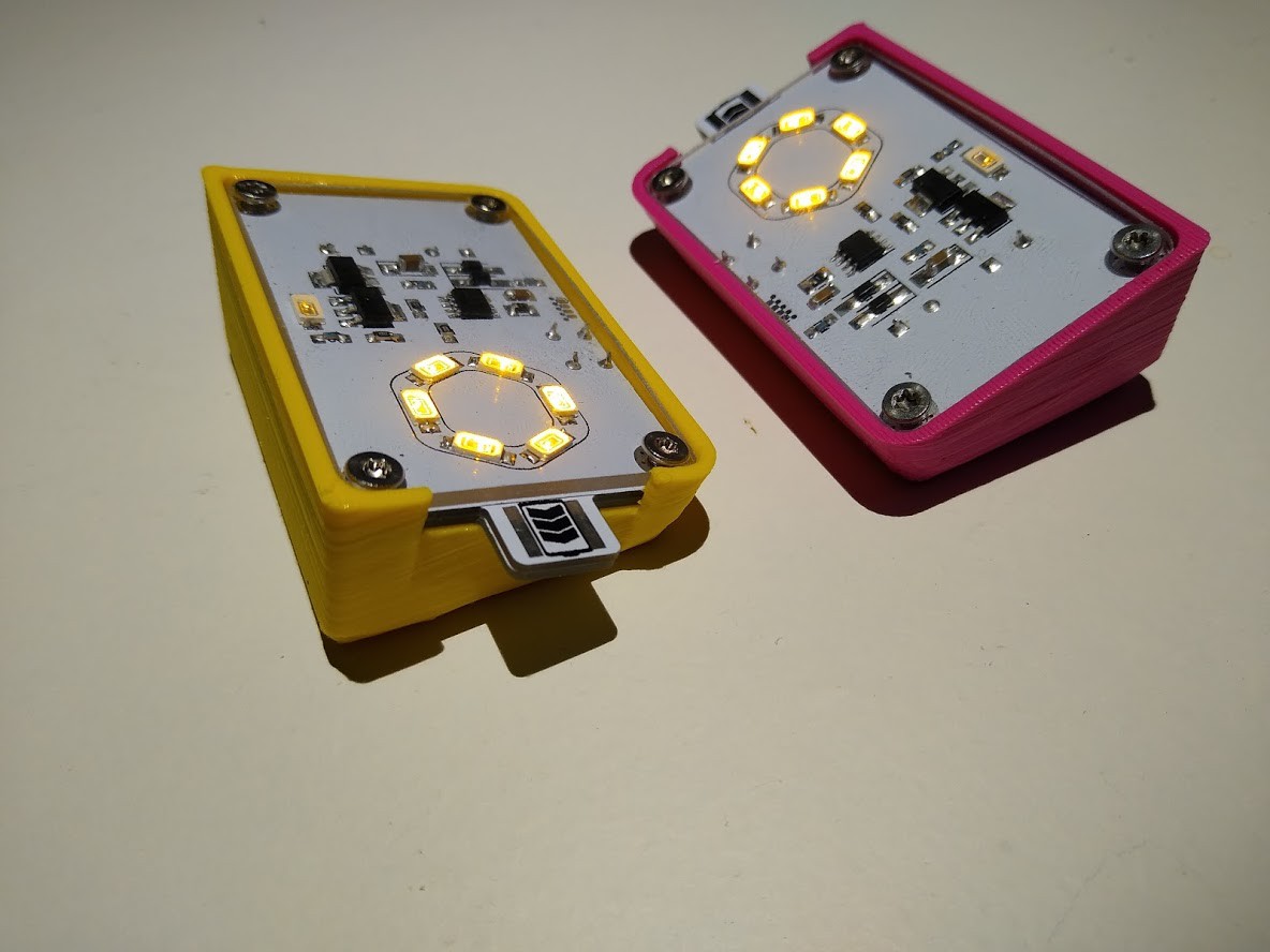
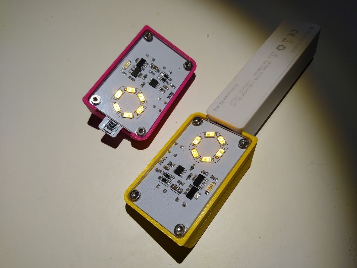
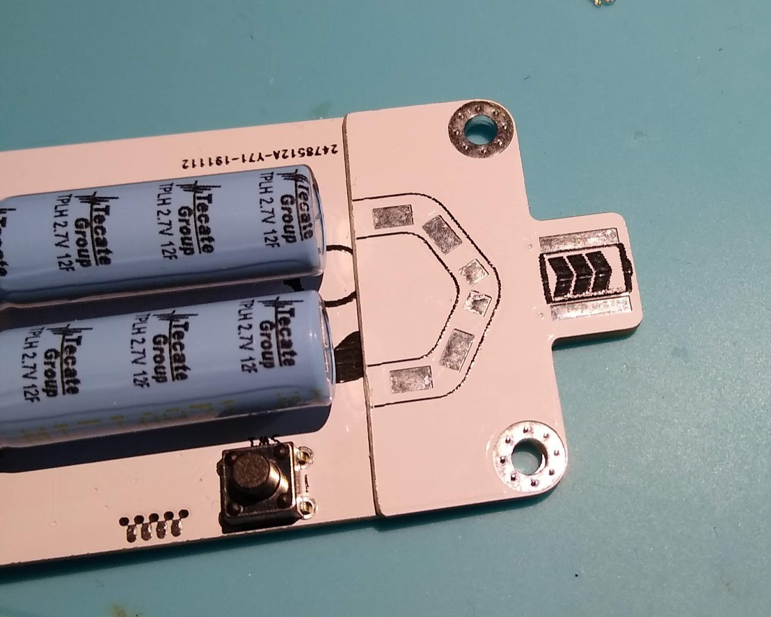
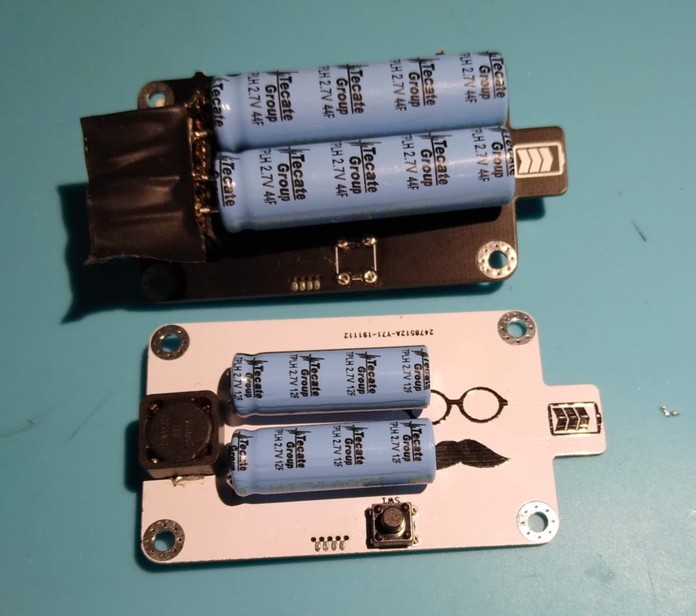
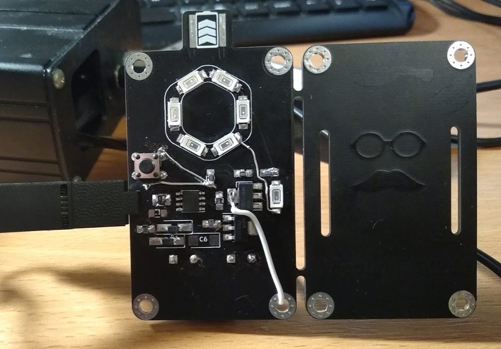
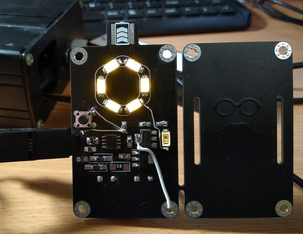
We're using supercapacitors in V1.3. None of this lithium nonsense. Who can be bothered to wait more than the time it takes to brush your teeth for your torch to charge? Just stick Yapolamp in your nearest USB power pack for blinky goodness in a couple of minutes.


Everything after this point refers to the original project ideas, since superceded in V1.3. Kept here for reference.

CONTROL

So, I want to drive an LED or two from a battery and have a timer to turn it off after a certain period. This will hopefully prevent battery drain if my son forgets to turn the thing to SLEEP mode (as there's not going to be a planned "off" mode). I'm aware that different modes could be achieved with a discreet component circuit but for me, a bare microcontroller with decent low power sleep and watchdog modes is what I'm after. Depending on the eventual feature set, I think an ATtiny85 should suffice and is available in a hand-solderable SMD package.

DRIVING LEDS

Driving LEDs is something I've tried before but not seriously moved beyond resistors to control the current. I've been amazed at how small a current can generate a visible light output but when I discovered @Ted Yapo's #TritiLED project, the care that has gone into eeking out the best photon per coulomb ratio is admirable. If I get stuck using the simple driver design from the V2 TritiLED, I'll go back to current-limiting resistors.

BATTERY LIFE

LED driving efficiency isn't really essential here - I do plan to use a decent 18650 with perhaps 3400mAh and compared to the ON mode, the energy lost in the resistors while minimal (microAmps) current is flowing is negligible. Most of the energy conservation will come from the auto-SLEEP feature that I currently envisage will start a timer when the torch is switched to ON and will modulate the light output after, say, 10 minutes. This alerts the user who then has two minutes to press the control button and reset the ON timer.

CHARGING

Using lithium rechargeable batteries in a "home-made" children's project presents some health risk. I'm going to have to work this one out and if I have to resort to alkaline or NiMH AA batteries in series, then that's an acceptable fall-back. I'd like to crack the (admittedly self-defined) problem of using a TP4056 but requiring a method of assurance that the charger and battery are connected to each other. I.e. I want to make sure someone hasn't...

Read more »

  • 1 × ATtiny85 (eventual main microcontroller) Microprocessors, Microcontrollers, DSPs / ARM, RISC-Based Microcontrollers
  • 1 × Inductor (LED driver circuit component) Playing with various values - 1mH, 3.3mH, 6.8mH, 10mH. Low ESR is desireable.
  • 1 × Optional - digital multimeter Limited utility in measuring the actual voltages and currents used
  • 1 × Optional - oscilloscope For useful analysis of the LED driver circuit - mine is a cheap DSO 138 kit and does the trick
  • 1 × Arduino Nano clone For convenient USB-enabled design work where I want to test code (e.g. edit the pulse lengths and frequency) conveniently

View all 13 components

  • Yapolamp V1.3 Ready for Christmas...

    Simon Merrett12/18/2019 at 23:49 11 comments

    ...mostly. There are still a couple of little details for the automatic turn off and a new feature I want to add to indicate when the supercapacitors have charged to full capacity (rather than waiting for any indicator LED on the USB battery bank to indicate that the #Yapolamp isn't drawing any more current).

    But I wasn't going to let those software defined features stop me from declaring V1.3 released! To recap, we have a 12F supercapacitor bank being charged with a transistor-based constant current circuit from (nearly*) any USB power supply. *I haven't tested all of them, so can't claim complete compatibility! It has reverse discharge protection diodes to prevent an inquisitive tongue placed on the PCB contacts from seeing any current (I have tested this - always go lead-free on the PCB finish for this kind of design!). The ATtiny402 controls an inductor flyback LED driver and a momentary push button is the only user input, to switch between a very low power "always on" mode, so the torch can be found in the dark, and a "full on" mode that allows dark-adjusted or light-adjusted eyes to navigate around a dark house or read a book. "full on" mode lasts 25 minutes with the 12F capacitors. Here's a comparison between "always on" and "full on" modes:

    The 3D printed enclosure is angled so that the torch can be seen on a bedside table, like an alarm clock, or laid on your chest or sheet to illuminate the pages of a book you're looking at in bed. The momentary push button is inverted, so the user just has to squeeze the screen into the enclosure to press it. 

    The PCB keeps all the components apart from the supercaps, button and inductor on the front surface and there's a 2mm polycarbonate cover over the PCB for protection, while allowing you to appreciate the internal components. 

    Charging a Yapolamp V1.3 takes a minute or two from any basic USB power supply.

    The PCB is 1.2mm thick and a second, shortened and unpopulated PCB is placed on the back of the USB connection segment of PCB that protrudes from the enclosure, as even a 2mm thick PCB isn't thick enough to get a good fit inside a USB receptacle. Two 1.2mm layers stacked is perfect: 

    My only downfall in this part of the design is that I put a copper ground pour on the back side of the PCB in the vicinity of the USB connector segment, so when the soldermask gets scratched off and if the user puts the connector into the USB pack the wrong way (easy to do), there could be a short of the USB power supply. So I turned the second piece of PCB over and the separated (and unconnected) pads are now what would be touching the USB connections if inserted the wrong way.

    Here's the release version of the PCB next to the awful greenwired one from last time:

    And you can see the significant space saving of the smaller 12F bank, compared to the experimental 30F (maybe 44F, depending on who you believe).

    There's a Ted in every torch*!

    It's time to wrap these two Yapolamps up for Christmas now. If there's interest, I'll share the files for the enclosure, PCB and tiny402 code.

    *with apologies to @Ted Yapo for getting the shape of both his glasses and moustache wrong. Clipart licensed for reuse is relatively sparse in those subject areas. I hope the homage is received warmly though.

  • Runtime

    Simon Merrett10/29/2019 at 21:04 2 comments

    I just ran the first full charge-discharge cycle of the latest Yapolamp

     with supercapacitors!

    Using the 30F capacitors (marked 44F but Digikey says they're 30F) and the somewhat below-maximum constant current resistor settings, I inserted the PCB USB connector into a 5V USB dumb battery bank. It took a minute or two to get the voltage up to 1.8V and then another 4 minutes to comfortably reach 4.8V. I topped out around 4.9V, which is good to see. The protection diodes were warm, at most.

    Then I reset and started the stop watch, hit the button to enter "full on" mode and walked away. Here's a photo from the 30 minute mark: 

    The final run time was just over an hour:

    62 minutes!

    I'm wondering whether smaller capacitors would be more suitable, for a shorter charge-time and run-time. The target user doesn't have much patience for things like charging, so I'm really pleased they take relatively little time to get up to full charge. The next size down is 12F, with a smaller 8mm diameter (as opposed to 12mm for the 30F ones).

    Comparing this 1 hour run-time and 4 minute charge timeto the first Yapolamp, powered by the 200mAh lithium pouch cell, it must have been absolutely churning through the Coulombs in a photonically* ineffecient way to discharge itself in the best part of 15 mins!

    *made up word, as I couldn't work out the conversion to Arbs.

    The PCB is largely updated for the re-spin, with only final checks to go. Code-wise, I would like to try and put a timer on this version, so it warns the user after a period that it's about to enter "always on" from "full on" and then does so, unless it receives a button press to keep it "full on". But in all honesty, it would be fine with the basic button-press to switch between modes.

  • If the cap fits... ...populate it.

    Simon Merrett10/24/2019 at 12:16 0 comments

    As predicted at the end of the last log, there were more mistakes learning opportunities with the latest version of the #Yapolamp. One of the tests I ran through was to connect the board to the power supply and ramp it up and down through the range of operating voltages I expect the system to see from the supercapacitors as they discharge.

    As I ramped up from 2.5V past 3.5V, I started to see strange behaviour. The system would work correctly in "always on" mode, the low power mode where the microcontroller sleeps and wakes periodically in order to quickly drive the LED, using the inductor and MOSFET, as normal. However, when I pressed the button to change modes, the "full on" mode would only stay on for a second or two before switching back down to the lower brightness "always on" mode. This also seemed to happen when the supply voltage went too low (around 2.2V if I recall correctly).  Here's  a scope trace of the feedback pin on the ATtiny402 at the moment it "gave up" and changed modes:

    I went back and compared the circuit of my PCB design with the breadboarded version it was based on. The forward voltage on the feedback voltage dropping LED was the same, the voltage divider resistor values were the same. Very confusing. Next, I compared the waveforms of both PCB and breadboard versions at the feedback pin, to see if there was a significant difference. My hypothesis was that something was causing the feedback voltage to fail to reach logic level thresholds (see discussion and comments in earlier logs about whether the analogue comparator would have been a better way to trigger subsequent MOSFET pulses) and somehow I had got lucky in the magic formula of my feedback voltage dropper/divider on the breadboard version that was somehow unsuitable for the PCB version. Here are the two feedback traces running concurrently (blue is breadboard version, yellow is PCB version):

    Well that blows my first hypothesis out of the water - the yellow trace is clearly spanning at least the same, if not a larger, range of voltages as the breadboard blue one. But there are some spiky edges to the PCB version trace - maybe that's part of the issue. I decided to hold a 1uF capacitor across the 10k ohm resistor that pulls the feedback pin to ground and for as long as I could reliably hold it in place, it seemed to sustain the "full on" mode for much longer (until my hand wobbled and I broke contact). So then I looked back at my green-wired PCB more carefully and in my haste/laziness noticed two unpopulated capacitor positions: 

    My next hypothesis was that all this inductor-ringing with no decoupling capacitor (C1) might be causing my poor ATtiny402 to be resetting, so I soldered two 100nF capacitors in C1 and C6. With both in place, I went back and ran the supply voltage sweep - happily, it now accepted 4.8V and maintained "full on" mode but sadly started having sporadic black outs below about 2V.

    This got me thinking about what the differences between the breadboard version and the PCB version. So I looked more closely at the breadboard version and noticed I had soldered a 4.7uF cap between the inductor and ground! I also registered that there is now a PTC resettable fuse in series between the supercapacitors and the inductor, which will introduce a few ohms of resistance. There's a chance that the instantaneous current draw when the MOSFET closes is causing heating/tripping issues with the PTC and that a larger capacitor (than the first 100nF) at C6 might help. So I swapped C6 for the same 4.7uF capacitor as on the breadboard and here's what the new feedback trace looks like: 

    The high spikes are definitely gone but the low trough spikes remain - but now I think the PTC "choking" current and C6 absence value are more likely what was causing issues. The black outs are now only apparent at 1.8V and because this is the voltage at which I want the user to recharge the torch, it's not a bad behaviour as...

    Read more »

  • The phantom inductor-disconnector strikes again

    Simon Merrett10/04/2019 at 19:34 6 comments

    The first and only version of Yapolamp to have been released into service with a child so far (Beta, or V1) stopped working at the end of last year and when I opened it up, I found it was still somehow pumping current round the LEDs without being able to store any energy in the inductor. Because the inductor had fallen off inside the enclosure. My confabulation is logged here.

    Now, the new PCBs are in, for what I hope will be the next version in the wild. About the only things which are the same about this version, compared to Beta, are the LEDs and the fact it uses electricity to make it go. I will admit up front that this is one of the worst PCBs I have designed. It looks fantastic in matt black silkscreen but boy have I missed some traces. The first thing I noticed was when I fired up Kicad to print a schematic for component placing and I had a quick look at the PCB layout. There were air wires! How?! There's no way I would have knowingly sent this to the fab unfinished. Then I remember trying to make some changes and I must have got distracted, failed to refresh things and then ended up with unconnected sections. 

    Thin and pasty. And a bit out of focus. The graphic homage to the project's namesake looks great on the back plate, with copper under matt black solder mask, and is hopefully subtle enough to spare him any blushes.

    I initially soldered it up with some chipquik low temp solder paste and a hot air tool, following around after with more paste and the soldering iron where I had managed to fluff small passives up etc. Then I got brave and added the super capacitors. These things are hefty - marketed as 30F but the insulation round the outside says 44F... I also addressed the airwires I could see needed a greenwire. Even though I will have to revise this PCB and throw it away, it looks so nice I even went to the trouble of trying to colour coordinate my greenwires with it. Then I tried to flash a program and bingo, the chip confirmed it was programmed. Then nothing happened. 

    Supercaps go in here. Well they would go in a bit further and then bend their leads so the cylinders are flat against the back of the PCB but I had a hunch that I would need to keep some spare lead on these caps for reuse in a fixed revision.

    Of course it did - these super capacitors are at 0V right now. So I set up with the power supply current limit on and tried to charge at the expected 500mA but the overcurrent protection kept kicking in. At 800mA (my diodes are rated for max 1A between them) I was still tripping the protection and I stopped. I had to change resistor values twice before I got anything under 500mA. This was around 260mA and I'm leaving this first build like that for now. It took a couple of minutes from memory to charge from 1V to 4.88V. Not bad but could be better. We can play with resistor values later.

    Sadly, the presence of 4.88V in the bank didn't cause photons to start flying, so I went back to Kicad and looked for the next mistake - no joy. Then I spied it - a trace from one net was driving straight over a pad from another net. How had I parted with money to make this junk?! But still no joy. I wanted to check I wasn't being let down in the code, so I uploaded a really simple 10 us pulse every 100 ms, BUT STILL NO LIGHTS!

    So I started probing for continuity on the board. At this point I knew my copper was a mess and I might get lucky and find out where. And when I flipped the board over and probed the inductor, I found that it was not connected to the MOSFET! WHAAAAAAT? One more greenwire to the rescue and bingo, photons leaked out into the room.

    Photons leaking out slowly. This is the "always on" mode. For contrast, compare the ring of six "always on" LEDs with the "off" one that I use to drop the voltage into my feedback pin that triggers the next cycle of charging the inductor.

    And, with the push of a tactile momentary switch, we are in "full on" mode. Notice the voltage dropper LED middle right is now on too, as it's...

    Read more »

  • We have a leak.

    Simon Merrett09/06/2019 at 10:16 0 comments

    You may have noticed a frothy amount of progress with the next version of #Yapolamp in June and July this year, and then a big pause. Summer holidays? No. Leaky circuit. When I tested the "full on" run duration of the test setup, which uses a 3F capacitor pair (in series to achieve 5V handling), I also tested the "always on" mode, where we put the microcontroller to sleep between very short, spaced out pulses that allow you to find the torch in the dark without depleting the capacitors significantly. 

    The problem was that I couldn't get 24h from this, even though in theory it was using waaaay less power, so I dug in a little deeper. It appears that my carefully thought-out constant current charging circuit, with anti-backfeed diode (to avoid zapped tongues if the charging connector ends up in someone's mouth...) was discharging my supercaps at a noticeable rate. In the following diagram from the schematic, you'll have to forgive the error in placing the caps in a 1S2P arrangement - we needed at least 2S for these supercaps to take 5V. Also, J4 and J11 would be closed/connected and J7 would be open/disconnected. They are test points.

    So where's the leak? I had my suspicions but it took a little while to be sure. It's the Schottky.

    Everyone will tell you about Schottky reverse leakage current but I didn't hear them or blithely ignored any mention of it. In the case of the diodes I was using, the ON Semi MBRA210LT3G, this is what is claimed: 

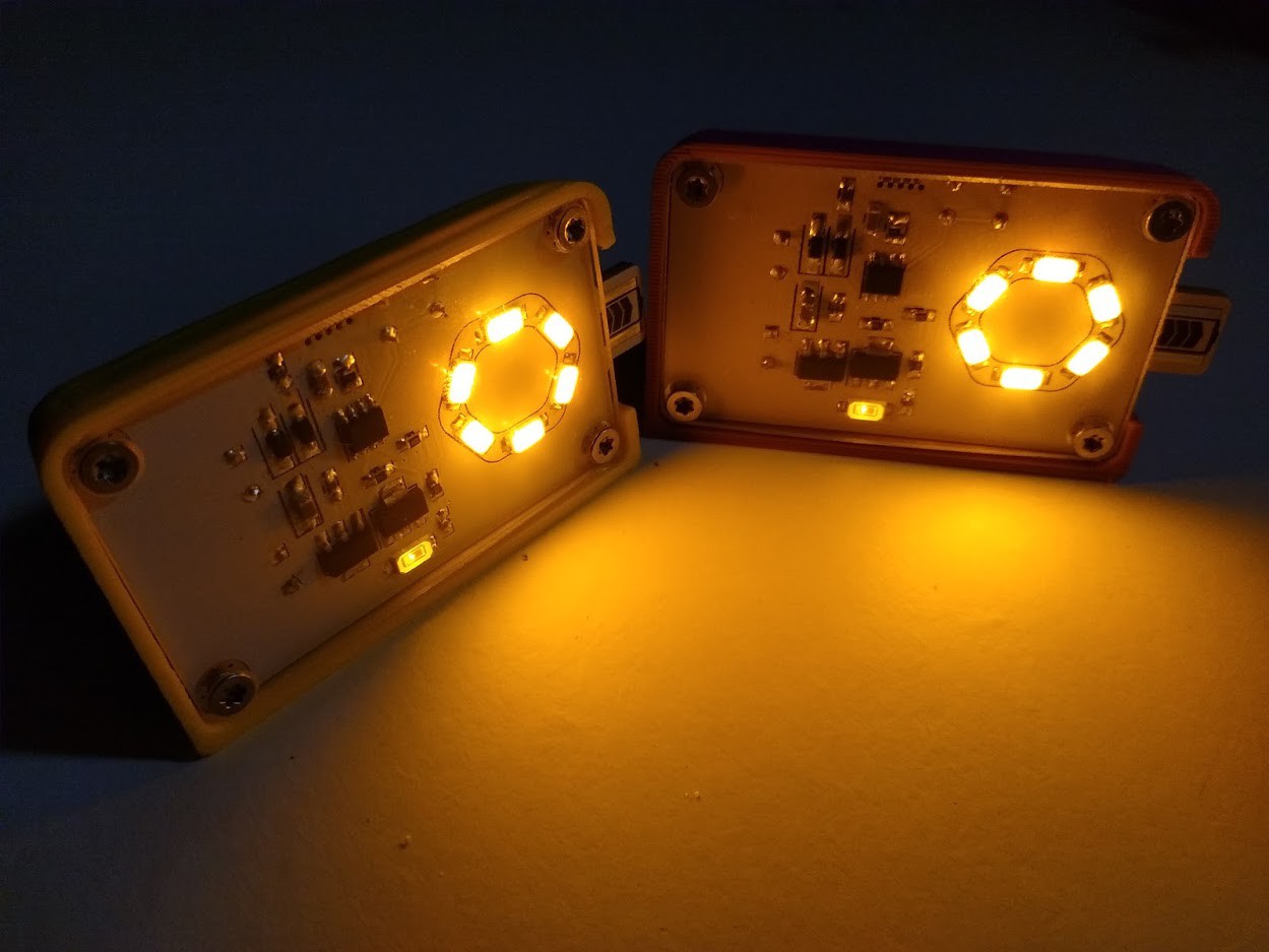
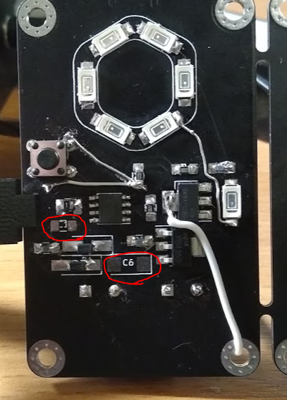
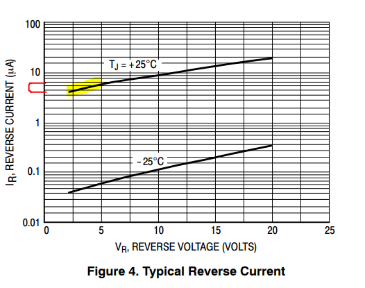
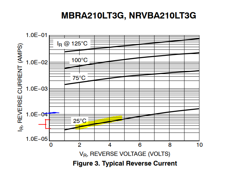
    We should be seeing between 30-70uA reverse current. My multimeter had it at 110uA, so that's disappointing. I started looking around for a better option. I thought there would be three obvious ones:
    • A better Schottky - how hard could it be to find one?
    • A normal diode
    • Some other anti-backfeed device, akin to the MOSFET-in-reverse protection against reverse polarity

    So, I couldn't find anything simple as an ideal diode that wasn't a bit expensive for this application (rail to rail opamp and a PMOS perhaps). A normal diode would be fine except that it means I can't charge the capacitors to as close to the 5V supply. This is annoying because I heard the higher voltage you go on a capacitor the more energy you store... But seriously, we can keep this as a backup version. I tried a normal diode and it did a grand job at preventing reverse current leakage. So, back to Schottky's. 

    One of the sad things about the parametric searches is that there is rarely a checkbox for "reverse current leakage at 1.8-4.8V between 10C and 25C". I noticed that you can have decently low forward voltage (tick!) but poor leakage (untick!). Or you can have "low leakage" diodes that have nA Ir (tick!) with Vf in the 1V range (untick!). Not to mention needing current carrying capacity. I could put a couple in parallel for my attempted 500mA charging current but I'm loathed to buy three or more for every torch, so that rules out another subset of parts.

    I think I now have a decent contender: the ON Semi MBR0520LT. Here are the claims:

    0.25-0.35Vf (tick!)

    5-8uA reverse leakage current (tick!)

    And 0.5A max current, so we may use a pair in parallel for our charging at half that max rate. Or perhaps charge more slowly.

    Anyway, I'm off to update the board and maybe one day soon we'll have a supercapacitor version of Yapolamp on the go!

  • Pulses, not pauses

    Simon Merrett07/19/2019 at 13:40 11 comments

    This could almost be a log for #The Rise and Fall of Pulses but we're operating in the microsecond range, which is a relatively geological timescale compared to those pulses!

    There's a certain amount of curiosity that drives this project along. The pulse generation is a point in case. As you may have noticed, I've recently been playing with the new-ish ATtiny402, a part that shares many of its peripheral and register settings with two families of parts the ATtiny 0 series and ATtiny 1 series. In theory, there's a huge amount of flexibility for an engineer to switch quickly between parts because the code will be so portable. In reality, the datasheets have suffered from what appears to be a relatively high degree of copy and paste, or at least the assumption of commonality hasn't been tested. This can mean that discovering how a peripheral needs to be set up for parts like this that don't have many readily published examples, can be a "voyage of discovery" to put it mildly.

    #Yapolamp needs pulses (although as I have pondered @Sander van de Bor's  #ATtiny Super Capacitor Spider which drives its LEDs purely with PWM to produce a fade effect, I wonder if protection against MOSFET failing ON could allow this to be a contender for the #Yapolamp . Anyway, I'm deep into the inductor driver rabbit hole at the moment and the delights of the ATtiny402 (not its datasheet, but the IC itself!) are more than adequately holding my attention. 

    You may recall that I used TCB0 on the ATtiny402 to generate a nice, duration controllable pulse on the Waveform Output (WO) pin, PA6. This was lovely because using another neat trick of the ATtiny402, I can measure the continually decreasing supply voltage from the supercapacitor to the circuit and automatically adjust the pulse to assure we were achieving the same sawtooth current profile throughout the full voltage operating range, which is over 3V. By controlling the current, I am happy that this is a proxy for brightness, so I don't need to "test" that we are maintaining the same light level across the range of supply voltage. I also chose this current profile because it represents the most efficient conversion of electrons to photons, according to my shonky tests.

    But all of this was using delay() and as I'm playing with the 402, why don't we see if we can generate the pause, after the pulse, during which we wait for the inductor to discharge through the LEDs, in a more convoluted way? Great, glad you're onboard with that. Options to do this with the older ATtinies would have included timers. Here's the timer option set for the 402:

    We have already committed TCB0 to doing duty on the single shot pulse generator, so that's off limits. We do have TCA0 on the ATtiny402, although this is reserved in the megaTinyCore for all the Arduino timing stuff, exactly like millis(), delay(), micros() and microSeconds(). So best not to mess with that for now (although you can mess with what you like if you can live with the consequences). The last one, the RTC, is a nice little thing not really with an equivalent in the older ATtinies. It runs from the 32kHz oscillator though, so the fastest period it has is 1/32000 or ~ 30us. My sawtooth discharge at 12-14mA takes around 10us, so we'd be extending total duty from between 30-60% (for 1.8v - 4.8V respectively) down to 25-50%. Maybe not drastic but I think we can do better, and there's no guarantee that we can actually do anything within a single RTC clock cycle. In fact, as far as I can tell from the dubious datasheet, the shortest Periodic Interrupt Timer is 4 cycles, plus whatever time it takes you to service that ISR, and the fastest you could do an event driven approach is 64 cycles. Not worth investing in for this use but definitely worth returning to, perhaps as part of #ATtiny 0 Series programming on the cheap

    Events, dear boy

    The new kid on the 0 and 1 series block is the core-independent peripherals. Core independent...

    Read more »

  • I love tiny-land and I never want to leave.

    Simon Merrett07/17/2019 at 15:11 0 comments

    After ensuring that one uses the unit of Arbs at every available opportunity, I'm well aware that the second rule of "science" is to change several variables at once, so you can be sure you will never really understand what happened but that if it's a good outcome you can carry on, smugly praising yourself for saving at least one iteration of work. If it doesn't work you can always go back to the way-of-the-sucker and change variables one at a time.

    Wrong MOSFET

    You know I told you all about that naughty OnSemi FDT439N that was operating far worse than its datasheet claimed, perhaps causing us to lose 20% of the usable voltage range of the supercapacitors? Erm, I may have used a different part. On closer examination, it appears I took some shortcuts with populating my Yapolamp 1.1 development board and an itinerant STN4NF03L may have sneaked its way onto the PCB both PCBs...

    So what? I took the opportunity to lash up the 1S 6P and change the MOSFET for a pukka FDT439N.


    Back to the bench

    I didn't change the timings on the pulses, and it's probably a good thing too. One thing I didn't notice in SPICE for the 6S 1P arrangement is the discharge duration is muuuuch longer (double, because half the Vf for 1 LED vs 2 LEDs in series). There's a roughly 20uS discharge period for this arrangement, as opposed to the other arrangement. We are getting into audible range of oscillation for the full pulse-discharge cycle but I didn't detect any noise (especially above the oscilloscope fan!). Here's the setup:

    Scores On the Doors

    I couldn't quite believe this but my little 3F supercapacitor bank (2 in series because I got 2.7V versions) ran down to 1.8V at some time after the 5 minute point. The reason I'm not sure of the time is that it kept running, that little ATtiny, lower and lower. Eventually, the LED brightness dropped a bit, but certainly not to an unusable level. The ATtiny402 kept going and going and going, until at 6 minutes and 42 seconds, the lights went out. What amazed me about this was not how the MOSFET mix up (and maybe the LED 1S 6P arrangement) had made such a difference, but that the voltage across the supercapacitors when the lights went out was

                                                        1.36V!!!!!!

    I love it here in tiny-land and I never want to leave.

  • Slowly moving to tiny-land

    Simon Merrett07/17/2019 at 11:46 0 comments

    This log is about transferring from pulsing the classic inductor driver with an ESP8266 that is powered separately (and therefore Vpulse = 3.3V, even when Vcapacitors = 1.8V) to an ATtiny402. It's no secret that I'm a fan of this chip but this phase took me to places in the datasheet I have never been before...

    The big news is that the megaTinyCore for the new 0 and 1 series ATtiny chips for Arduino is available. More details coming soon on my #ATtiny 0 Series programming on the cheap project but somehow having the ATtiny402 in the Arduino IDE just helped me speed things up with development. At the moment, while the core is new, I do still check if something that breaks on the Arduino IDE side works on Atmel Studio before admitting it's my fault!

    BLUF

    The 2S 3P arrangement doesn't take kindly to Vpulse < 2.4V. This means we're losing 0.6V/(4.8V - 1.8V) = 20% of our anticipated operating voltage range. This won't necessarily translate into 20% of our run-time but it is significant.

    But First

    Before we get into the goodness of the microcontroller, there are issues to report... Since last time, I have implemented a quadratic calculation for the number of microseconds the pulse should last for any given voltage. It works well (until brightness drastically drops off at 2.4V. I have tried altering the equation to significantly increase the pulse duration approaching 1.8V (from 17uS to 40uS) to no avail.

    What could the cause be? Well, my first instinct was the MOSFET, although this part (OnSemi FDT439N) is rated for a VgsThreshold of 0.67V typical and 1V max. I could understand it complaining about 1.8V perhaps but I would expect 2.3V to be fine... This seems a likely contender because immediately that I swap the pulse back to 3.3V, the LEDs do brighten, although not as good as they should be.

    I realise that we're getting to some very low voltages for discrete silicon parts that I can buy and solder together, but I was somewhat disappointed to find that 30% of my voltage range has gone missing! 

    My next contender for disappointing component is the inductor. It has resistance, so reduced voltages are going to struggle more. Not sure. What I do know is that I saw the inductor voltage trace on my oscilloscope struggle and then fail to reach the required voltage to discharge through two LEDs in series, as Vcapacitor passed below 2.4V. Which gave me an idea to revert to the no-no of driving LEDs - 1S manyP.  Hold that thought.

    The Burden of Control

    In the last log, when I reported a 4mins 30second run-time, I was careful to caveat that this was not paying for the energy used by the pulsing microcontroller; it was just the LEDs drawing from the supercapacitors. This time, I whipped out my trusty (totally untested) ATtiny402 and tried to get some pulsing going. I set the clock to 5MHz, which is deemed safe down to 1.8V, turned brown-out detection etc off and got it blinking. I managed to get it down to running at 1.5V in this mode and 1.7V at 10MHz but YMMV and there was hysteresis, ie you needed a couple of hundred mV above those to restart, once it crashed. Not for the faint-hearted. I do wonder what you could get down to while running the internal 32kHz oscillator and consuming less than 10uA. maybe a shiny new single AAA cell would even be able to get one going at 1.5V... Ah, distractions...

    Anyway, after impressing me with the operating voltage, I re-tuned to  5MHz and gave it some pulsing on the LED driver MOSFET gate. Success. That last couple of sentences makes it sound way easier than I found it but that's my fault for insisting upon learning how to do single shot pulses using TCB0 on the ATtiny. There's a thread on AVRfreaks alluding to my woes and recording the code which works for me. I hope to recount my tales of TBC0 and Event System glory on the #ATtiny 0 Series programming on the cheap project one day. I had forgotten that although the peak sawtooth current is 14mA per LED, that equates...

    Read more »

  • Auto-pulse, auto-brightness

    Simon Merrett07/15/2019 at 12:52 0 comments

    Last time we noted that the 2.2mH inductor was going to need long pulse-discharge periods to drive the planned 6x LEDs for the next version of #Yapolamp . I thought I would go for a 1mH inductor but plumped for a 680uH one instead. I ordered it a while ago and can't remember why I picked it - probably price!

    Dynamic Pulse Calculation & Generation

    Now the pulse durations required for the 680uH inductor driving 6x LEDs at the most efficient sawtooth profile (see previous log) vary almost inverse proportionally to the voltage of the supercapacitors that are powering this version. I took the pulse durations calculated by spice at 1.8V, 3.3V and 4.8V, which represent the lower, nominal and upper operating voltages that I expect. I then measured the ADC counts for the 3.3V (actually 3.29V) and 5V (actually 4.82V) rails on the Wemos D1 mini R2 when put through my 2.2K/2.2K Ohm voltage divider. I put them into Excel and used a linear trendline (to start with - we can always improve this) to work out how to calculate a pulse duration for every voltage between 1.8V and 4.8V.

    So using this, we can make our pulse calculation code as follows:

    pulseOn = 25 - ((analogRead(A0) + 21) / 42);

     The  /  42 is the equivalent to * 0.024. I add 21 to the ADC read because 21/42 = 0.5 and because integer maths rounds to a floor, rather than normal rounding, adding 0.5 has the effect of implementing normal rounding (both up and down, rather than solely down).

    Results

    This works! From a fully charged pair of 3F supercapacitors in series at 4.85V, the discharge brightness is pretty even over the full range of voltages down to 1.8V. Here's one of the moments that the pulse duration is increased to maintain the peak sawtooth current (as indicated by the increased duration of the discharge of the inductor in the trace):

    I set the ADC-based recalculation of the pulse length at 10Hz and this seems fine for adjusting the pulse (brightness) not only during the discharge but also the MUCH faster charge phase - that's right, this torch can be fully-on with constant brightness during charging of the supercapacitors from the USB battery bank!

    This test also now allows us to better estimate the run-time for a given capacitor charge. Bear in mind that we will have to add in the microcontroller current burden to the calculation but from this experiment, our 3F capacitors give us a 4 mins 36 seconds run time from full to 1.8V (and the LEDs are still bright at this point - just can't be sure the microcontroller will keep going below this voltage). 

    Auto-pulse points to address in future:

    • There's a slightly detectable increase in brightness at each increase in pulse duration. Ideally, find a better way than delayMicroseconds() to time the pulse lengths. This will rather depend on the final microcontroller and its configuration (clock etc). 
    • The discharge duration sits nicely in the 10-12 uS range for voltages above 2.1V but below this, it drops a little low. This could be improved by adopting a non-linear function to calculate pulse durations from ADC counts. Again, because of ADC non-linearity etc, there's little point in optimising this with the ESP8266 (which was never a contender for the final uC but has 3.3V GPIOs for test pulse generation) and I'll wait for the final microcontroller before improving this.
    • You will see in the GIF of the oscilloscope trace above, that the point when the next pulse opens the MOSFET is not well-matched to the inductor voltage's lowest point, wasting some energy. This could be improved as an optimisation but I don't think it would make a significant difference to run-time and efficiency. Please disagree with me in the comments and perhaps it will motivate me to compare!

    Next steps

    So now I have proved we can achieve a constant-ish brightness from a wide range of supply voltages, I'm confident we can now start to design a more compact PCB for a V1.1 beta (oh dear - will we ever leave beta-land?!). However, before that,...

    Read more »

  • Scaling Up

    Simon Merrett05/14/2019 at 08:27 0 comments

    In the last log, we created the pulses to generate the most efficient peak sawtooth pulse currents to drive the LEDs and compared the brightness of the most efficient LEDs to the existing Beta model of the #Yapolamp  which is driven by an anomaly (go see what I mean) and it's LEDs get hot and are a different colour tone to the efficiently driven ones...

    In concluding that we needed to go brighter with the efficiently driven LEDs, we created higher peak sawtooth currents by pulsing the same 2.2mH inductor for longer (pulsing means opening the MOSFET and letting current begin to build between VCC and GND, which builds the magnetic field in the inductor). Checking back to the efficiency curves, we seem to be losing 9% of our Lux/mA (or Arbs) if we drive at 20mA peak sawtooth current. There was a noticeable increase in brightness but they still weren't as bright as the Beta.

    Which brings us to the latest test: will efficiently driven LEDs produce sufficient light in a bank of 6 to meet the aim:

    1) A torch for the user to find their way around a dark room or for limited reading under a duvet. 

    ?


    So with an array of 6 LEDs in a 2 Series, 3 Parallel (2S 3P) arrangement, we need to go back to Spice. The 2S 1P circuit we used previously is on the top and the 2S 3P is below:

    Here, we can see the effect of the same pulse applied to both circuits: 

    Note that the current going through the 2S 3P is approximately 1/3 of the 14 mA peak in the 2S 1P (as expected with Kirchoff's law). Both discharges start and end roughly the same time. To get the 2S 3P arrangement operating at 14mA peak sawtooth current, we need to pulse the MOSFET much longer, about 3x longer (everything's looking nicely linear at this point). In this plot, we're pulsing the 2S 3P circuit for 25.5us and I have delayed the start of the 2S 1P pulse so that the discharge curves are superimposed:

    See how the 2S 3P (turquoise) discharge period is about 3x longer than the 2S 1P (red), making our whole cycle duration about 57us. This means that the fastest pulse-discharge frequency is 1/0.000057 = 17.5kHz. This is in the upper range of audible sounds, so we could have a problem with the device whining in use. If we shrink the inductance, we can reduce the pulse length required to generate our peak currents and also commensurately this will reduce the discharge time across the LEDs for a cycle. For example comparing two 2S 3P LED circuits below, one with the original 2.2mH inductor and one with a 1mH inductor, we can see they can both be pulsed and achieve 14mA peak sawtooth discharge:

    This time the turquoise trace is the LED attached to the 1mH inductor and the green trace is attached to the 2.2mH inductor. We can read from the traces that a total pulse-discharge cycle for a 1mH inductor takes about 27us, which isn't an exact division by a factor of 2.2 but is close enough. The resulting frequency for a 27us cycle is 1/0.000027 = 37kHz, which is sufficiently above audible spectrum that I'd be happy with this.


    For now, until I buy a 1mH inductor (good, there are plenty to choose from in this size) I can use the 2.2mH to test brightness of the 2S 3P arrangement

View all 30 project logs

Enjoy this project?

Share

Discussions

Ted Yapo wrote 07/12/2017 at 13:35 point

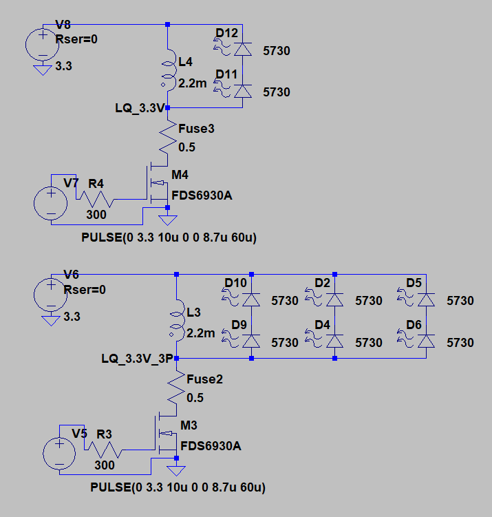
Hi Simon, I just wanted you to be aware that there's a serious failure mode associated with the basic design of the MOSFET/inductor boost circuit.  If the MOSFET is held on, the inductor is basically shorted across the battery.  This could cause very serious damage to the circuit and surroundings, especially with a high-power battery such as you are using.  The MOSFET could get stuck in a conducting state through a number of failure modes, including software errors, software corruption (cosmic rays happen), or if the gate is left floating due to tri-stated uC outputs (even during reset).  I discuss one solution to this in a TritiLED log:

https://hackaday.io/project/11864-tritiled/log/62286-safer-tritileds-one-simple-trick-prevents-catastrophic-failure

but this may not work if you also want a high-power mode.  Just a heads-up, because I didn't see this at first, and it definitely should be addressed.

  Are you sure? yes | no

Simon Merrett wrote 07/12/2017 at 13:43 point

@Ted Yapo, thank you for making sure I'm aware of that risk. I have read your post and I am using a 10k pull down resistor on the MOSFET gate in the current Yapolamp design. Do you think a resistor in series with the inductor and led is also required/sensible or will controlling the gate with a pull down be sufficient? 

  Are you sure? yes | no

Simon Merrett wrote 07/12/2017 at 13:51 point

I see now, after reading again, that the series resistor is really worth having in case the uC pin fails high. If cost is lower priority than safety, I wonder if having an npn transistor between the gate and ground, with the base tied to the uC pin via capacitor, with a pull down resistor, would work. If the pulse is short then the capacitor doesn't charge enough to open the transistor and pull the gate low, but if the uC pin stays high, the capacitor charges, the transistor starts to conduct and the gate is driven low.... 

  Are you sure? yes | no

Ted Yapo wrote 07/12/2017 at 19:31 point

Yes, I think the uC pin sticking high is the real risk.  It could be as simple as the oscillator stopping (for whatever reason) mid-pulse.  It's probably a rare occurrence, but the consequences could be very bad.

I see where you are going with the transistor gate shunt idea - to limit the pulse width, essentially.  I think some kind of current-limiting element in series is probably the safest approach.  It might be as simple as a picofuse - they make them down to 62 mA rated current:

https://www.digikey.com/product-detail/en/littelfuse-inc/0251.062MXL/F2307-ND/700687

The currents go up from there - I'm sure you could find one that would protect all the elements in your device while still allowing the power you require.  This will work better than a simple resistor for the higher-powered lamp you are developing.  At the power levels I care about, the efficiency loss with a resistor is tiny.

  Are you sure? yes | no

Simon Merrett wrote 07/12/2017 at 20:48 point

A fuse popped in to my head about 5 mins after my last reply - great minds... 

  Are you sure? yes | no

Simon Merrett wrote 05/30/2017 at 18:58 point

Thank you to everyone who likes/follows #Yapolamp. In a bid to save everyone's feeds getting clogged, I'll do it once, here.

  Are you sure? yes | no

Similar Projects

Does this project spark your interest?

Become a member to follow this project and never miss any updates