 Simon Merrett
I'm mystified. I now have the prototyping board to try out supercapacitor power and compare the MT9284 driver scheme with the original inductor boost circuit. I decided to tear down the original Yapolamp Beta (I know changing from Beta to V1.X isn't helpful). As you may remember, the whole impetus for a V1.1 was that the original had stopped working. Here's what I found:
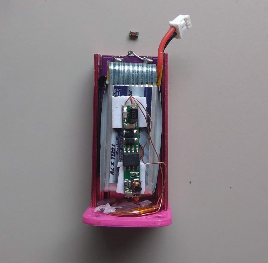
That cheeky little inductor I was so keen on for its low profile has completely come away. I think I'll share the blame for poor soldering with the fact that the bonding pads on the inductor were probably not designed to be dropped as much as the Yapolamp has been. It was nestled in behind some PVC insulation tape I had lined the enclosure with, thankfully not causing any short circuits with my lithium battery.
Now for the weird stuff.
So then I happened to touch the two pads where the inductor should have been with a finger and the Yapolamp glowed into life!
WITH NO INDUCTOR!
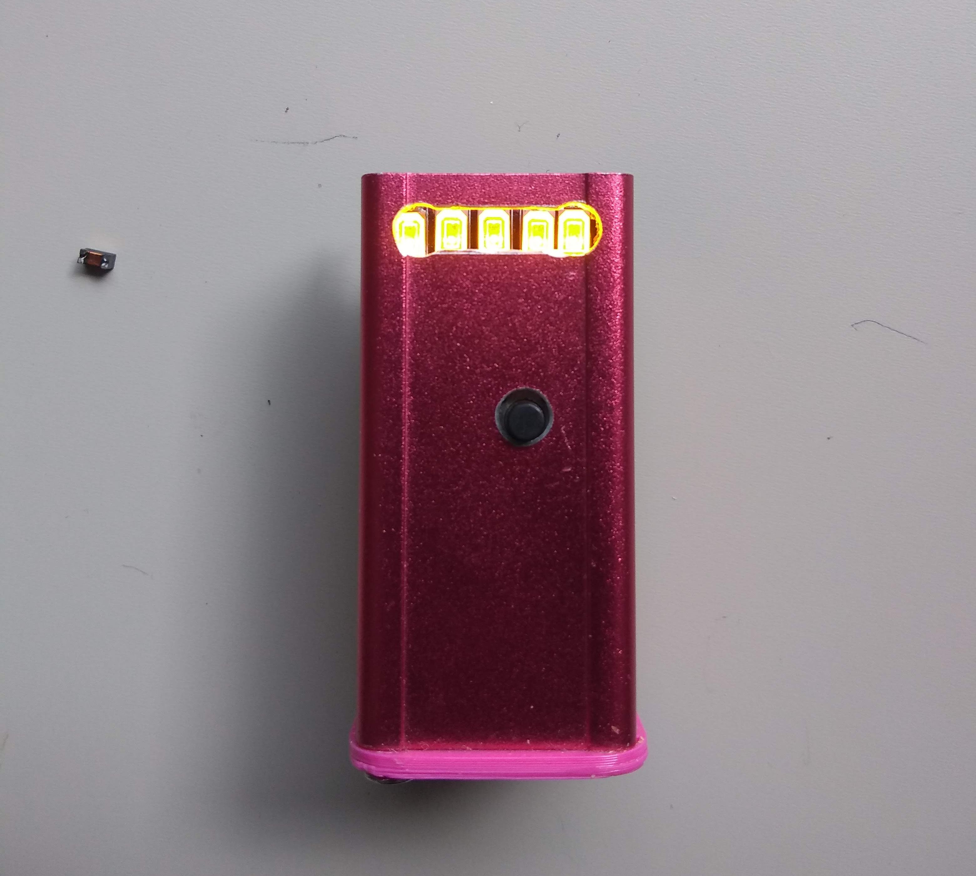
It didn't just glow, it had full function. Button presses cycled between the always-on and full-brightness modes. I left the full-brightness mode on and sure enough, after several minutes it started to blink to signal to the user that it would be turning itself back to always-on mode if you didn't press the button again...
WHY IS THIS WORKING?
I can understand the ATtiny85 running properly but how can the reverse-connected LEDs be driven if they're not connected at one end and the other is only connected to Vbat? Inductor PCB pad acting as a capacitor? Ideas gratefully received in the comments...
<EDIT> Hopefully you can see the pictures now @Ted Yapo - I think I used a link from Google photos. They're now uploads.
Now I'm even more confused. Here's the schematic from last December:
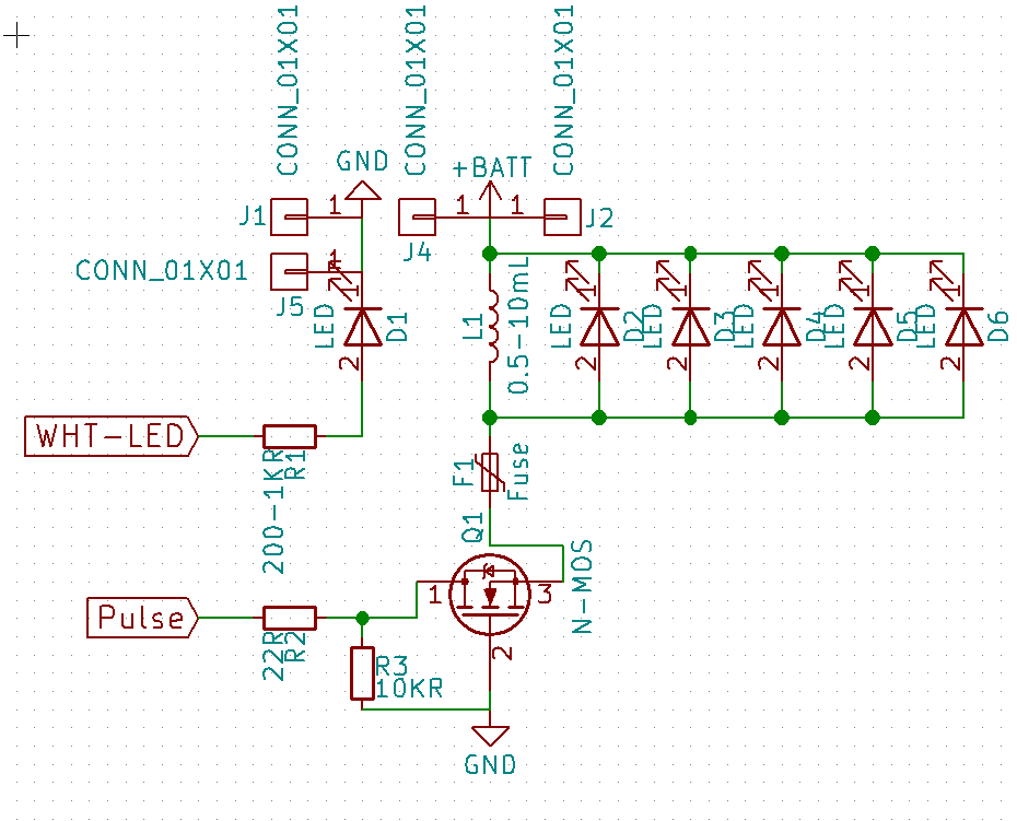
Ignoring that white LED (which I never felt the need to fit) and the fact that I shorted across the fuse terminals, can you spot the error? Yep, that N channel MOSFET appears to have a pulse driving the Drain, with the Gate pulled to Vdrain by a 10k resistor and the Source at the same voltage as the LED anode... how is ANYTHING working here!?!
</EDIT>
Discussions
Become a Hackaday.io Member
Create an account to leave a comment. Already have an account? Log In.
Your images don't show up for some reason.
Are you sure? yes | no
Hi Ted, sorry. Should be fixed now and I've added a little "schematic surprise" which I hadn't spotted until forced to go back to it after 12 months in use...
Are you sure? yes | no