 agp.cooper
Front Panel
I added an 8 bit front panel to the schematic:

The Front Panel maps 128 bytes of PROM, 120 bytes of RAM and 8 bytes of IO. So I thought I better do the Monitor Program before I went any further as the PROM for the Weird CPU was only just enough.
The first problem was that writing to the IO port involves a read first and I had not anticipated that. Two fixes, make the port a register or map the port to a RAM address.
The second problem is that as I use momentary contact switches, I need an XOR to toggle the bits in the Data and Addr variables. As SUBLEQ has no hardware bit operations I wrote some C code with pseudo SUBLEQ code:
char xor(char a, char b)
{
  char c=0;
  char w=0;


  loop1:
    // c=c+c
    subleq(c,&z);
    subleq(z,&c);
    subleq(z,&z);


    /* TEST 1 A<0 AND B>=0 */
    // Test A<0
    subleq(t,&t);
    if (subleq(a,&t)) goto TEST1A_GEZ;         // TEST_GEZ
    if (subleq(t,&t)) goto TEST1B;             // TRUE_LTZ
    TEST1A_GEZ: if (subleq(1,&t)) goto TEST2;  // TRUE_GEZ
                                               // TRUE_LTZ (-128 found)
    TEST1B: // Test B>=0
    subleq(t,&t);
    if (subleq(b,&t)) goto TEST1B_GEZ;         // TEST_GEZ
    if (subleq(t,&t)) goto TEST2;              // TRUE_LTZ
    TEST1B_GEZ: if (subleq(1,&t)) goto SETBIT; // TRUE_GEZ
    if (subleq(t,&t)) goto NEXT;               // TRUE_LTZ (-128 found)


    TEST2: // A>=0 AND B<0
    // Test B<0
    subleq(t,&t);
    if (subleq(b,&t)) goto TEST2B_GEZ;         // TEST_GEZ
    if (subleq(t,&t)) goto TEST2A;             // TRUE_LTZ
    TEST2B_GEZ: if (subleq(1,&t)) goto NEXT;   // TRUE_GEZ
                                               // TRUE_LTZ (-128 found)
    TEST2A: // Test A>=0
    subleq(t,&t);
    if (subleq(a,&t)) goto TEST2A_GEZ;         // TEST_GEZ
    if (subleq(t,&t)) goto NEXT;               // TRUE_LTZ;
    TEST2A_GEZ: if (subleq(1,&t)) goto SETBIT; // TRUE_GEZ;
    if (subleq(t,&t)) goto NEXT;               // TRUE_LTZ (-128 found)


    SETBIT:
    subleq(-1,&c);


    NEXT:
    // a=a+a
    subleq(a,&z);
    subleq(z,&a);
    subleq(z,&z);
    // b=b+b
    subleq(b,&z);
    subleq(z,&b);
    subleq(z,&z);
    // w=w+w+1 - Avoid -128 bug
    subleq(t,&t);
    subleq(w,&t);
    subleq(t,&w);
    subleq(-1,&w);
    subleq(t,&t);
    if (subleq(w,&t)) goto loop1;
    return c;
}
I had lots of problems with underflow (i.e. the value -128) which took time to solve. The problem is that -(-128) == -128! The code is efficient and could be adapted to other bit hardware (i.e. AND, NAND, OR, NOR and SHR). The code works out the word width by itself.Unfortunately the code is about +34 instructions or +102 bytes long! I will need to add a hardware XOR to the schematic if I want to stay with 8 bits.
Test A >= 0
This test must be popular for SUBLEQ coders as it is only two instructions and A is not modified:
- subleq t t ?
- subleq a t JGEZ
- ...
Here is a true A >= 0:
- subleq t t ?
- subleq a t TEST_GEZ
- subleq t t TRUE_LTZ
- TEST_GEZ: subleq 1 t TRUE_GEZ
- TRUE_LTZ: ...
Does it really matter that we should always use the true A >+ 0 version? Consider the C code for loop:
- for (char i=-128;i<=127;i++);
The compiler will not mind (quite legal) but after counting from -128 to 127 it repeats infinitely.
It appears as if it does not matter that the comparison in the for loop fails.
Coding Conventions
In the above pseudo code I have used the z (=zero) convention of ensuring it is set to 0 after use. Where I can not do that I use t (=temp) where it must the zeroed before use.
Two other coding conventions would "n" for -1 and "p" for +1.
Synthesizing Arithmetic
I found a great site that helped with the general structure for XOR subroutine. Worth a look:
http://bisqwit.iki.fi/story/howto/bitmath/
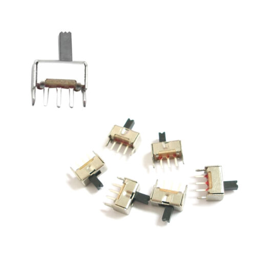
Switches
Oh well, I am forced to use PCB mount slide switches:
 So the Monitor pseudo code would be:
- Initialise
- LOOP:
- Read the IO Data register (the switches) to the DataIn variable
- Read the IO Addr register (the switches) to the Addr variable
- Write the Addr variable to the IO Addr register (the LEDs)
- Move the data from the memory pointed to by the Addr variable to the Data variable
- Write the Data variable to the IO Data register (the LEDs)
- Compare the IO Data register to the DataIn variable, if equal then go to step 9
- If Addr variable equal 0xFF then exit Monitor and go to 0x80 (i.e. run the user program)
- Move the IO Data register to the memory pointed to by the Addr variable
- Wait 10 ms for switch debounce
- REPEAT
Note: The move operation using the Addr variable as a pointer requires self modifying code and must reside in RAM.
Monitor Code Fail
I could not fit the monitor code in the allocated 128 bytes:
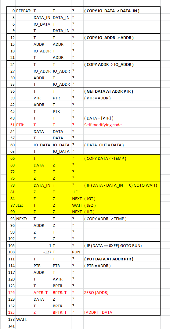
Its only a rough outline (the WAIT has not been coded) so some optimisation will help but not enough to make it fit. And I still need to move the self modifying code into RAM. A basic composite instruction (i.e. COPY) is about 12 bytes of memory. This compares to 6 byes for the transport Triggered Architecture (TTA) of the move only Weird CPU, and I thought that was inefficient!
The remaining option is to use an Arduino to program the CPU if I want to stay with 8 bits. One way to do this is for the Arduino to drive the !Reset low and to gate the !WE and !OE signals.
The other option is to step up to 16 bit.
Staying with 8 Bits
I will rework the decoder to allow an Arduino to take control of the bus for programming.
For input/ouptut the CPU will take to the Arduino.
AlanX
Discussions
Become a Hackaday.io Member
Create an account to leave a comment. Already have an account? Log In.