 Elia
EliaThe antenna uses 'choc block' type screw terminal connectors that are held to the boom by zip ties. They allow the individual elements to be slid in and secured in place with a screw driver by tightening the screw terminals.
When it's time to pack up the antenna can be broken down by loosening the screw terminals and sliding the elements out of them. This allows the antenna to be broken down into the boom and individual elements for compact storage and easy transportation.
After cutting the elements to length, the elements were centered inside the screw terminals and a strip of electrical tape was wrapped around each one to mark how far it needs to be slid inside the screw terminal for easy assembly in the field later on.
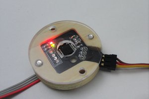
A clever trick I used to allow the driven elements to be easily disassembled as well is to design a PCB that adds a female SMA connector to each driven element so they can be connected to the diplexer using readily available SMA pig tails. The PCBs are soldered to the driven elements in the same locations as the coax would be in the traditional design.
The diplexer is not shown in the images, check the WA5VJB PDF for diplexer component values & schematics. Same goes for element lenghts and spacings.


 ottoragam
 Marc-André Denis
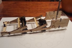
 Jeremy Ruhland
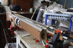
 FiveseveN
These are some great ideas on construction! Thanks.!