 w_k_fay
I am working on a VFD clock project and I needed a way to vary the brightness of the display. The VFDs are either too bright or too dim on a fixed voltage. They also have a tendency to ghost at high voltages which is very noticeable in low light. (old VFD calculators use a tinted lens to eliminate this)
Some builders use the microprocessor to dim the display at specific times of day but I want my clock to respond to the ambient light. I considered many schemes with the microprocessor PWM output and an LDR for a sensor. All of these ended up with some high side switching topology that was overly complex and inefficient. The simple solution was to vary the output voltage of my existing MC34063 based power supply.
The MC34063 must be the Swiss Army knife of power supply chips as it can buck, boost or invert voltages. With an external transistor it can provide even higher currents and voltages. There are several online and downloadable calculators that will help you select the various components you need to create just about any small power supply you might need, from a couple of volts up to hundreds of volts.
The output voltage is set by comparing the voltage of a resistor divider to the chip's built in 1.25v reference. With that said change the divider and you change the output voltage. The voltage is able to rise to many hundreds of volts at a current sufficient to kill you a few times over. SO BE CAREFUL calculate and double check any changes you plan to make before hand. This is essentially the same circuit used to generate 180v for nixie tubes and 400v for decatrons.
See https://threeneurons.wordpress.com/nixie-power-supply/ for the original version of the nixie supply
See http://timewitharduino.blogspot.com/2013/10/high-voltage-power-sources-for-tubes.html for a great selection of nixie and VFD power supplies.
See http://imajeenyus.com/electronics/20111010_40-400V_supply/ for a 40v to 400v variable high voltage supply based on the MC34063.
BE WARNED : THESE HIGH VOLTAGE SUPPLIES WILL HAPPILY KILL YOU IF YOU GIVE THEM HALF A CHANCE
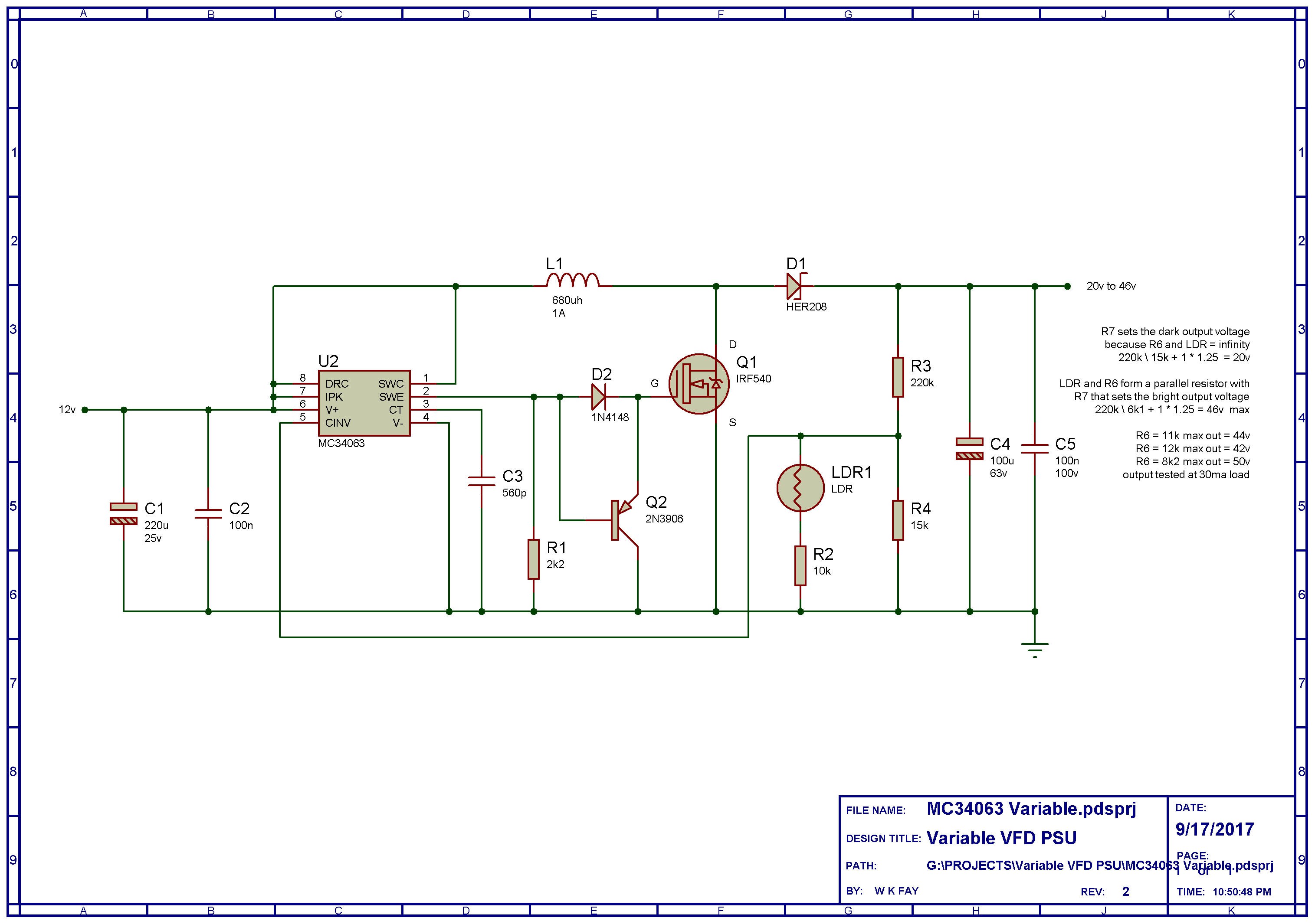
From the schematic you can see that we have an MC34063 with an external transistor. For outputs below 40v the external transistor can be omitted. Q3 helps to turn the MOSFET off more quickly. On the breadboard Q3 improved the efficiency of the circuit from 50% to 65%. On a well laid out PCB the efficiency might be closer to 70%. The distance from the chip to Q1 should be as short as possible. The MC34063 is not the most efficient chip but it is cheap and readily available. I regret ever suggesting that this chip is easy to work with. PCB testing has shown that PCB layout is critical to proper functioning of this circuit. What worked well on the breadboard did not work so well on the PCB. Many hours of trouble shooting and two PCB layouts later I had the circuit functioning properly. Short wide PCB tracks and testing may be necessary to get acceptable performance from this circuit. Place the feedback network as close to the chip as possible. Remote mounting the LRD will likely cause you problems.
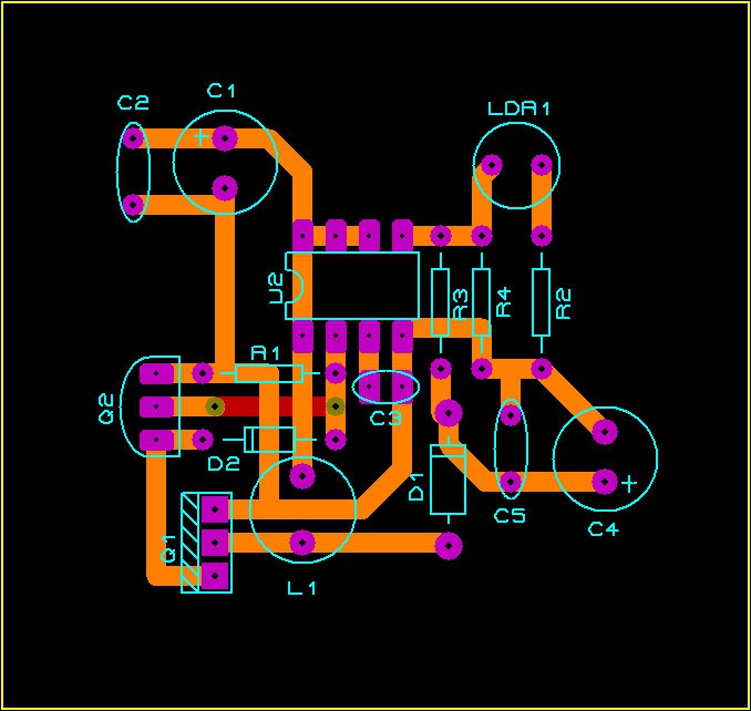
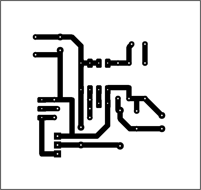
Below is a PCB layout I have build and tested successfully.
The LDR , R2 and R4 form a voltage divider with R3. The chip will adjust the output voltage to get 1.25v at pin5 which is connected to its internal comparator. In total darkness the LDR is essentially infinity so the lower half of the divider is just R4. The formula for calculating the output voltage in darkness is ( R3 / R4 ) + 1 * 1.25v and in this circuit that gives about 20v.
To calculate the output voltage in full sun we must find the total resistance of the LDR, R2 and R4. The LDR has a resistance is about 300 ohms in full sun and it is in series with R2, giving us 10k3. The 10k3 is in parallel with R4 and this gives us a total resistance of 6k1. So the bright voltage is (220 /6.1) +1 * 1.25 giving us about 46.5v . Changing R6 to 8k2 will give you an output of about 46v.
A FEW NOTES ABOUT BUILDING...
Read more »
 Sagar 001
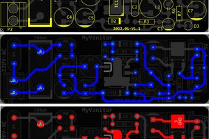
 hesam.moshiri