0%
0%
E4000
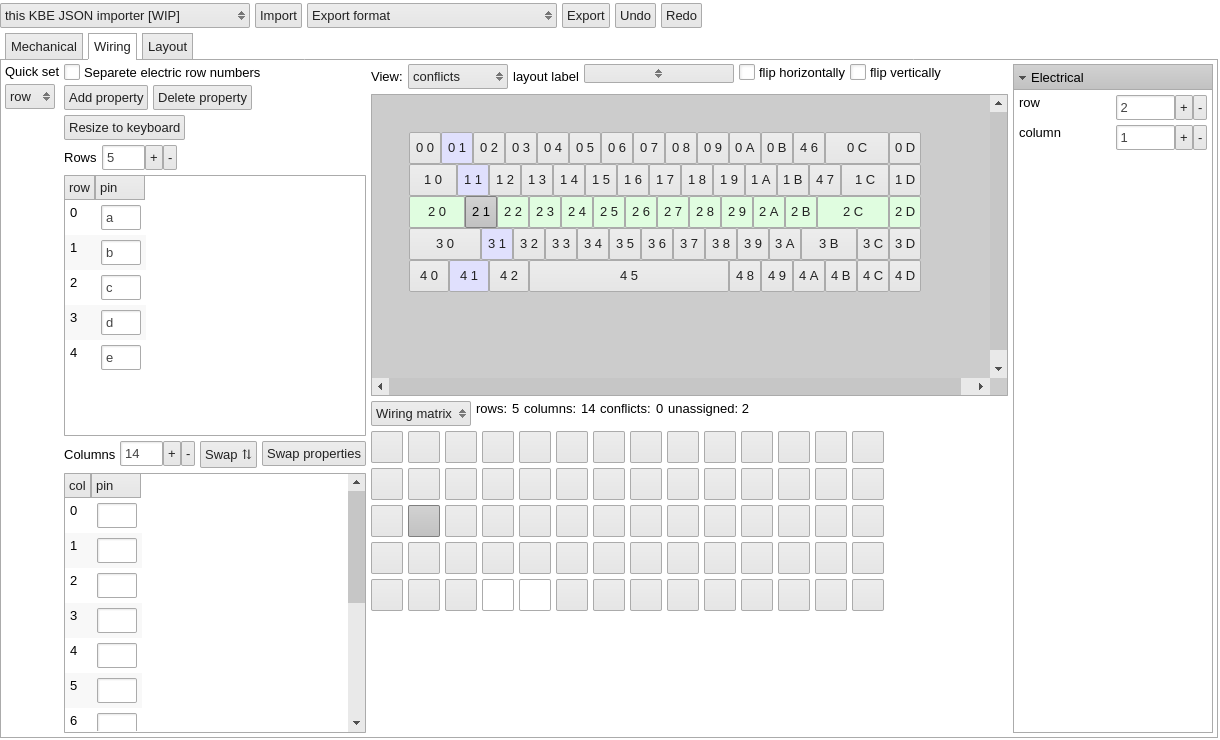
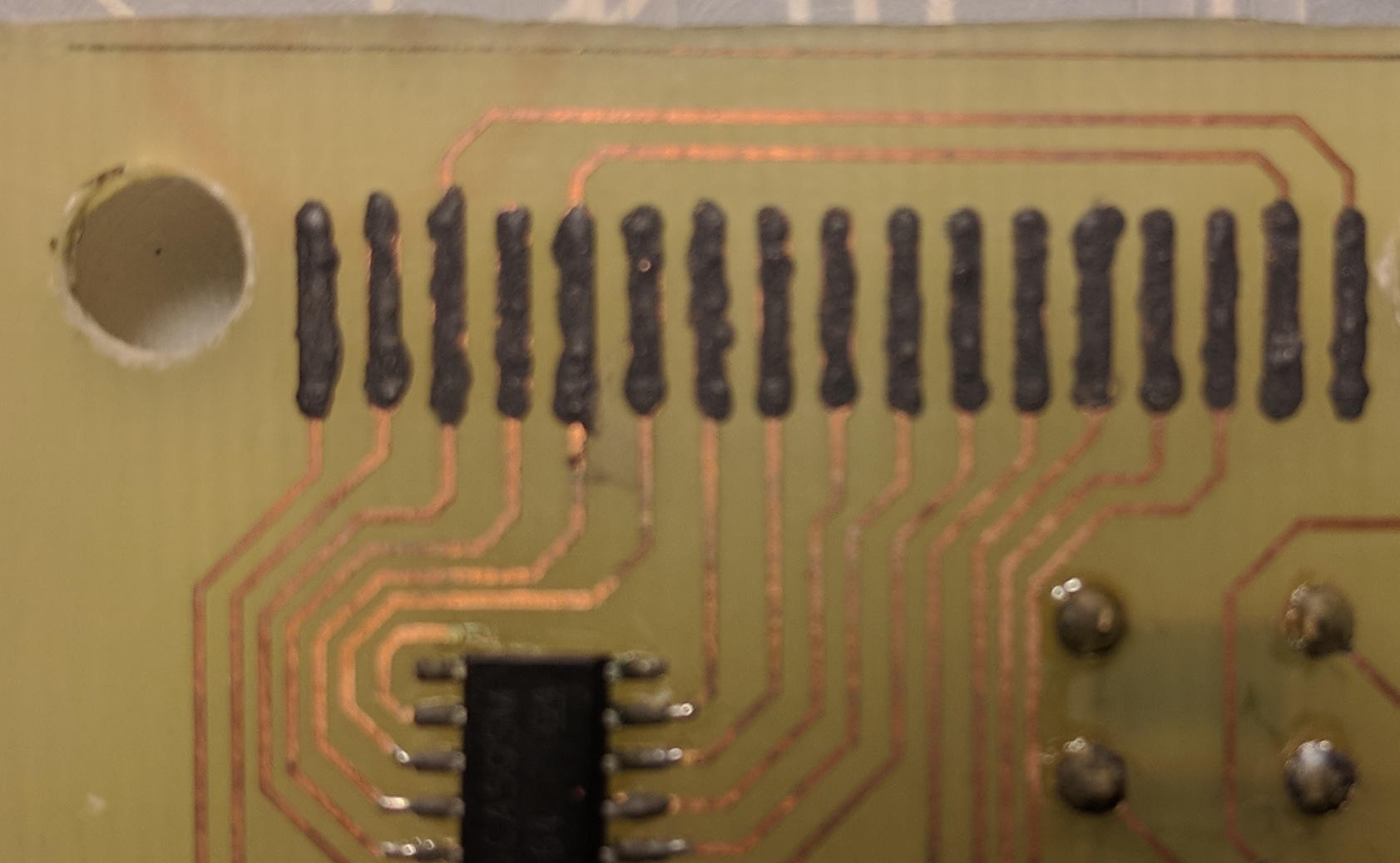
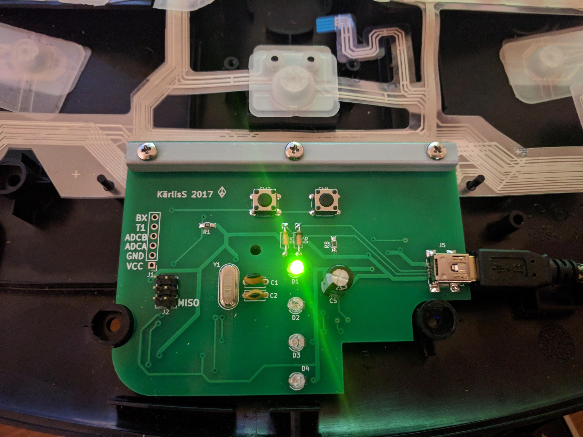
Replacement board for Natural Ergonomic Keyboard 4000 with joystick support.
 Kārlis
Become a Hackaday.io member
Already have an account? Log in.
Just one more thing
To make the experience fit your profile, pick a username and tell us what interests you.
Pick an awesome username
hackaday.io/
Your profile's URL: hackaday.io/username. Max 25 alphanumeric characters.
Pick a few interests
Projects that share your interests
People that share your interests
 thpoll
 RasmusB
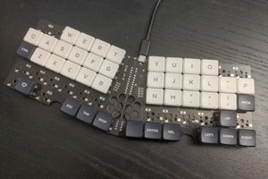
 deʃhipu
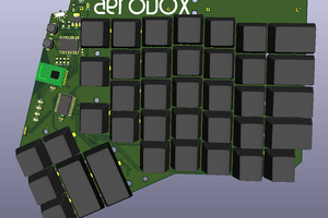
 Simon Merrett
Hi, nice start.
Did you get anywhere with this project? I'm thinking of "modding" my 4000, too