Objectives
Since I am relatively new to the sub-GHz radio world, I decided to start with a single application: Control a Ceiling fan and then take what I've learned and grow it into a more general tool. The first generation is transmit only and while it can be made to work from 300-900MHz, it requires changing components to do so.
For the first generation hardware the goal's I made are:
1. Control a ceiling fan with integrated light from a phone.
2. Set a schedule for the fan to turn on or off.
3. Focus on minimal UI and feature set (It's just a ceiling fan afterall)
Background
Based on what I can find online pretty much all the wireless ceiling fans sold in America use a 304MHz signal for control. The remotes typically use a simple On-Off-Keying with a pulse distance encoding which is very similar to infrared remote controls. Sadly, I was unable to find a 304MHz transmitter so I built my own based on a SAW resonator.
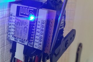
To provide the WiFi control, I went with an Electric Imp module which has WiFi and an integrated MCU with an RTC for running the schedules.
Protocol
The first step was to reverse engineer the fan protocol. To do this, I opened up a remote and found the signal which went from the MCU to the RF amplifier (the transistor that's next to the antenna). I put a scope on the trace and started hitting buttons. Sure enough, the protocol is very simple. Logic 0 is transmitted as 640us low followed by 320us high and Logic 1 is transmitted as 320us low followed by 640us high. Every button press creates a 13-bit transmission in the form of 0-1-[DIP1]-[DIP2]-[DIP3]-[DIP4]-0-[FanHigh]-[FanMed]-[FanLow]-[FanReverse]-[Light] where DIP* is equal to the settings of the DIP switches on the transmitter which acts as a 4-bit address so you can have 16 fans in your house. Each packet is transmitted 3 times with a 11ms pause between each transmission.
Hardware
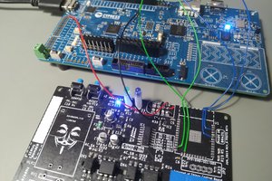
For the RF transmitter I copied the SAW-stabilzied reference circuit from RFM.
Since I wanted a small-ish wall powered gateway, I used the Electric Imp reference design Sophie which is a base board which could contains an AC/DC power supply and 3V3 power supply. I copied the board outline for the Electric Imp reference design Sana and added the transmitter. The WiFan board stacks on top of the Sophie board, though sadly this didn't leave enough room for my antenna in the box so it got all squished up.
The only changes from the schematics are that I added a 10pF series capacitor to the antenna, I hand wound my antenna and I grounded the antenna at the far side. This makes it behave more like a loop antenna, but increased my singal quite a bit. For the antenna length, I looked at a commercial 433MHz antenna and tried to make mine 42% longer, but it ended up a bit of a mess.
Software
I used the Imp agent to serve up a small webpage which has a selection of buttons to control the fan (see screen shot). The imp then formats a SPI packet to contain the On-Off-Keys and transmits the packet 5 times (I found 5 times to be more reliable than 3).
Check out the git hub link for the full source.
Next Steps
I'm very happy with the first generation, it is able to control a single fan but the range isn't very good, it can't be used in different frequencies without changing components and it is TX only so the learning process is very manual. The next generation is going to replace the SAW transmitter with the SI4460 RF transceiver.

 Pedro Minatel
 Keri Szafir
 M@lte
M@lte
 novirium