proximity controlled sampler
A sampler that is controller by a proximity sensor
A sampler that is controller by a proximity sensor
To make the experience fit your profile, pick a username and tell us what interests you.
We found and based on your interests.
test upsample downsample wav.pyprogram that upsamples and downsamples an audio file "test.wav" to understand how resampling worksplain - 20.16 kB - 06/21/2017 at 16:59 |
|
|
filter.pypython script to simulate the low pass filter, sinc windowed filterplain - 2.23 kB - 06/11/2017 at 08:15 |
|
A friend is making a electric bike and he would like the bike to have a sound like one with a combustion engine, so I am trying to adapt this project for this purpose.
In this video the engine sound is looped continuously.
The plan is to play a sound when the motorbike is tuned on to simulate the engine starting, then loop the engine sound with a rate proportional to the throttle or the motorbike speed and play a third sound when the motorbike is turned off.
This is my first test of the sampler controlled by hands movements:
I found out that if the pitch is controlled by the speed of the hand getting closer to the sensor makes the sound sound weird as it is difficult to maintain a constant hand speed.
For this reason, I choose to control the pitch with the position of the hand: Lower hand = higher pitch
My current development is this:
- Read a WAV file from the SD card (I tried to use a CH376 chip to read the file from USB thumb drive without success so I take the road of reading the data from SD card directly with the micro-controller)
- Re-sample the data using a low pass digital filter (I have rewritten this code 4 times: first time i simulated it in python on PC, second time i wrote in C for the PIC24 micro-controller, third time i wrote in assembler for PIC24, fourth time i used a dsPIC33 and learned the DPS assembler instruction set for it )
- save the re-sample data to external 64Mbit SPI flash memory. (I found out that in my application is faster to bit banging SQI (Serial Quad Interface) than using the SPI at maximum clock of 15 MHz)
- the dsPIC33 reads the re-sampled file and plays it back at a sampling rate variable between 88.2 and 176.4 Khz (after the DAC is advisable to have a low pass analog filter to filter out the DAC steps, this analog filter is more simple to implement if the sampling frequency is higher)
Right now the playback speed is limited between 1/8x to 2x of the original but I am going to extend this to 1/8x to 8x.
I have optimized a part of the code that re-samples the audio file, specifically the one that makes the convolution with the Sinc signal to low pass filter the audio file.
The code in C is:
for (i=0;i<nTaps;i++){
out+=(int32_t)inbuffer[i]*FilterTaps[i+FilterOffset[Ratio]];
}
This code takes 348 uS for a filter with 465 taps, this is the time needed to calculate the value of just one sample of the filtered audio signal.
The code below in assembler takes 28 uS to do the same thing
asm ("MOV #0xfffe, W0"); #0xfffe is the tap value
asm ("MUL.SS W0,[W1++],W2");
asm ("ADD W2,W4,W4");
asm ("ADDC W3,W5,W5");
These four instructions are repeated for every tap so no loop is needed. Is a waste of program space but i have plenty. The PIC24 i am using does not have multiply and accumulate instructions for DSP. If I will change to a dsPIC33 those 4 instructions should become one and the processing time should become 28uS/4=7 uS
I have made a test program in python "test upsample downsample wav.py" to understand how the re-sampling process works.
The program uses a FIR filter with the coefficients calculated with the online tool Tfilter: http://t-filter.engineerjs.com/
The program takes as an input a wave 16 bit mono file and outputs 6 wave files :
8X upsample
4X upsample
2X upsample
1/2X Downsample
1/4X Downsample
1/8X Downsample
Then I tried to port the same program on the PIC.
Probably i have exaggerated with the number of taps of the filter as i have 117 - 233 and 465 taps for my three filters. Ah, I have used the same filter for 2X upsample and 1/2 downsample, 4X and 1/4X, 8X and 1/8X.
I found out that to convert a sample of about 2 seconds it takes 15 minutes to the PIC with my NOT optimized program!
As the PIC has to read and write the values from the external flash memory a small part of this time is used for this but most of the time (about 90%) is used by this loop:
for (i=0;i<nTaps;i++){
out+=(int32_t)inbuffer[i]*FilterTaps[i+FilterOffset[Ratio]];
}
that is the convolution of the filter with the signal.
The PIC24 i am using does not have multiply and accumulate instructions for signal processing. I am now trying to optimize the code writing it in assembler. This part does not need to be in real time but 15 minutes is too long. I am also considering the option to switch to a dsPIC33 that has the MAC instructions.
In this project the PIC micro controller has to playback the audio sample with different speed, lower and higher than the original sampling frequency.
From a first test test, with a code not really optimized, the PIC can access the memory (in any location), read a sample and send it to the DAC at a rate of more than 90 M samples per second.
My idea is to store the audio sample in a external SPI flash memory re-sampled at different rates.
For examples these rates could be: 0.25x 0.5x 1x 2x 4x etc...
The original audio sample is sampled at a rate of 44 K samples per sec and stored in the memory in the "rate 1x" table.
If it is needed to playback the sample at a speed of 1.5x the PIC will read the memory where it is stored the original sample (rate 1x) at 44/1x1.5=66 K samples per second.
If is needed playback at speed of 3x the PIC will read the memory where is stored the re-sampled audio at a rate of 2x with a speed of 44/2*3=66 K samples per second.
And so on. The playbacks speed will vary continuously according to the speed of the hand above the infrared sensor so the PIC should have the possibility to jump between different tables continuously.
In this moment I am studying how to convert the audio samples in different sampling rates. It is not a trivial thing but my advantage is that the program in the PIC will need to compute this only one time and save it in memory so it does not need to be real time.
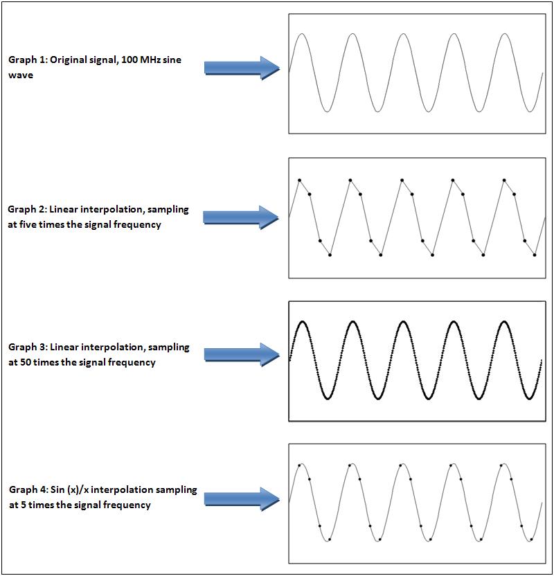
To re-sample is necessary to filter the signal with a low pass at about half the sampling rate in the case of increase the sampling rate.
To intuitively understand why it is necessary i copy this picture:
Now i am tying to understand the digital filter simulating it in python before write the actual program for the PIC.
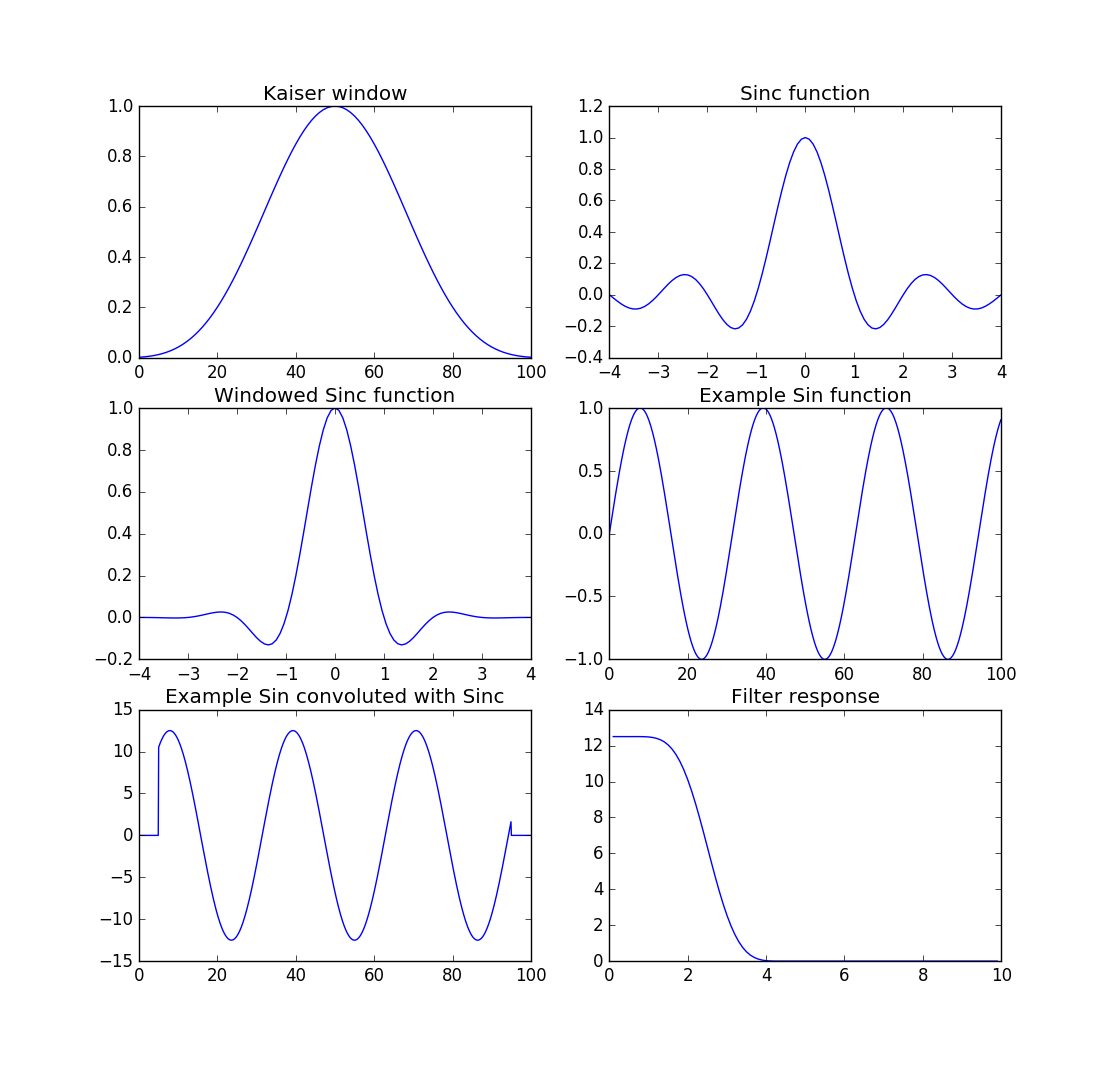
Then the same process is repeated changing the frequency of the sin wave. The filter response plot has on X the sin wave frequency and on Y the peak values of the filter output.
I am trying to understand if it necessary to apply the same process even when reducing the sample rate or it is enough a moving average filter.
I am doing this project using a PIC24EP32GP202 in a DIP package.
I found myself short of pins and I am thinking to use a bigger brother in a SMD package. Using this PIC in DIP package i found out that is very sensible to the layout, for example it does not work on a bread board because the connections to decoupling capacitors are too long, it keeps resetting, if it mounted in a socket with all the connections soldered on a prototyping board it works fine.
This PIC runs at 140 Mhz using a PLL and a quartz of 8Mhz (in my case)
I would like to try the SMD version with more pins and use an adapter to develop the project but I worry about the following points:
Will the length of the connections to the decoupling capacitors be too long and have the same problems i found using the bread board?
As the length between the PIC pins and the quartz will be too long, can I use an external oscillator and supply the signal at logic level to the PIC to overcome the distance problem? In this case I will use a 12 Mhz oscillator and obtain 140 Mhz using the internal PLL.
Any suggestion is very appreciated.
Create an account to leave a comment. Already have an account? Log In.
Become a member to follow this project and never miss any updates
 Bruce Land
 Raymond Lutz
 Scott Bragg