 Danie Conradie
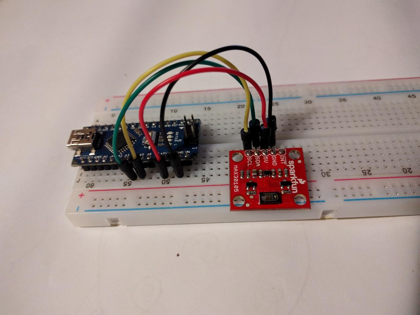
I played with the MAX30105 breakout from Sparkfun to see what it will take to measure heart rate optically. The sensor has a red, green and IR LED and based on the amount of light reflected back to the sensor it should be possible to do, among others, optical heart rate sensing. Although the MAX30105 is technically a particle sensor, as far as I can tell from the data sheets it is identical to the MAX30101. The MAX31010 is specifically a heart rate sensor according to Maximum Integrated, but the only difference in the datasheet is the name and descriptions of some of the registers.
The Sparkfun Arduino library for the MAX30105 makes it quite easy to start up the sensor and start testing. An example sketch is included to measure heart rate, so that’s what I used. I’m not here to reinvent the wheel, right? The sketch makes use of the amount of reflected IR light to determine when a heartbeat occurred. Below is a graph showing the values for reflected IR measured while holding my finger on the sensor.

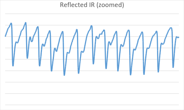
The graph clearly shows a repeating pattern in the measured reflected IR values. A bit of signal processing later and the sketch spits out a heart rate. This all looks great, but this project will not be used under laboratory conditions. These results were measured with me sitting still and keeping constant pressure on the sensor. Even in these ideal conditions, notice on the second half of the graph that the whole signal gets shifted up and down a bit. This is due to slight pressure differences of my finger on the sensor, making slightly more/less IR get reflected. Some signal processing could probably easily take care of slight differences in pressure on the sensor by detrending the signal or using a similar process.
The sensor would need to be fixed/held to the animal’s skin to enable measurement. If the device is worn as an ear tag, the sensor could be placed on the skin inside the ear. This would probably be the easiest place to access skin with little hair that could make measurement difficult. If the complete device is worn around the neck, wire will have to be run from the collar to wherever the heart rate sensor is placed. This does not seem practical or durable for livestock. The skin on the inside of the ear will also be thin, with the blood vessels close to the skin, which should also improve the result. I'm guessing thin skin will yield more accurate results than thick skin.
Some last thoughts relating to the use of optical heart rate measurement in practical applications: given conditions where the sensor can measure good quality data, optical heart rate sensing seems quite viable. The difficulty will lie in placing the sensor in such a location and fixing it in place reliably so that good data can be captured. This will have to be solved through trial and error and attaching the tag to an animal.
Discussions
Become a Hackaday.io Member
Create an account to leave a comment. Already have an account? Log In.
Continue on the project? It works very well. I'm working on this. I usually think of heat, accelerometer and magnetometer. I will use RFM95W. I am working with Atmel 628p. I am testing the sensors with kits. What I really want is to place the device in the mine. This means that the battery is used for more than 6 years. The current flow, for many years ... there is no risk of breaking the device.
http://www.livecare.xyz/new/sub2.asp
Are you sure? yes | no