 rawe
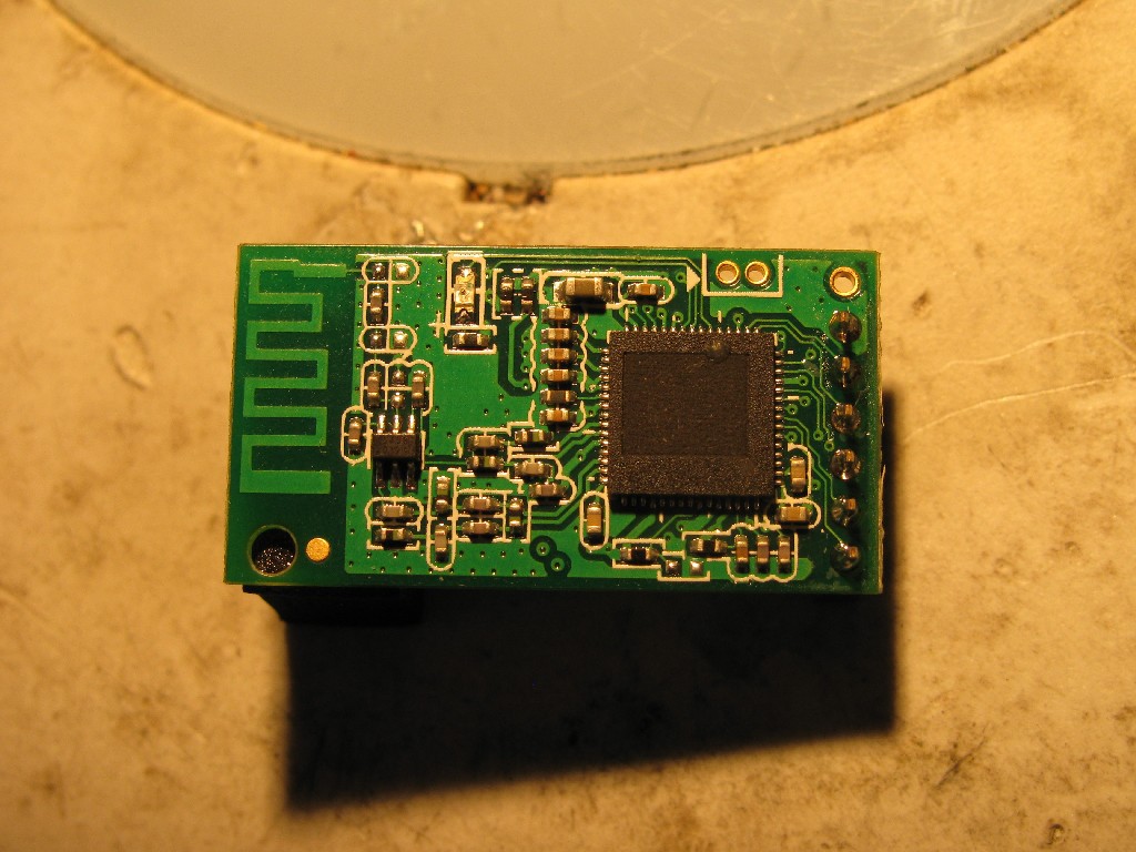
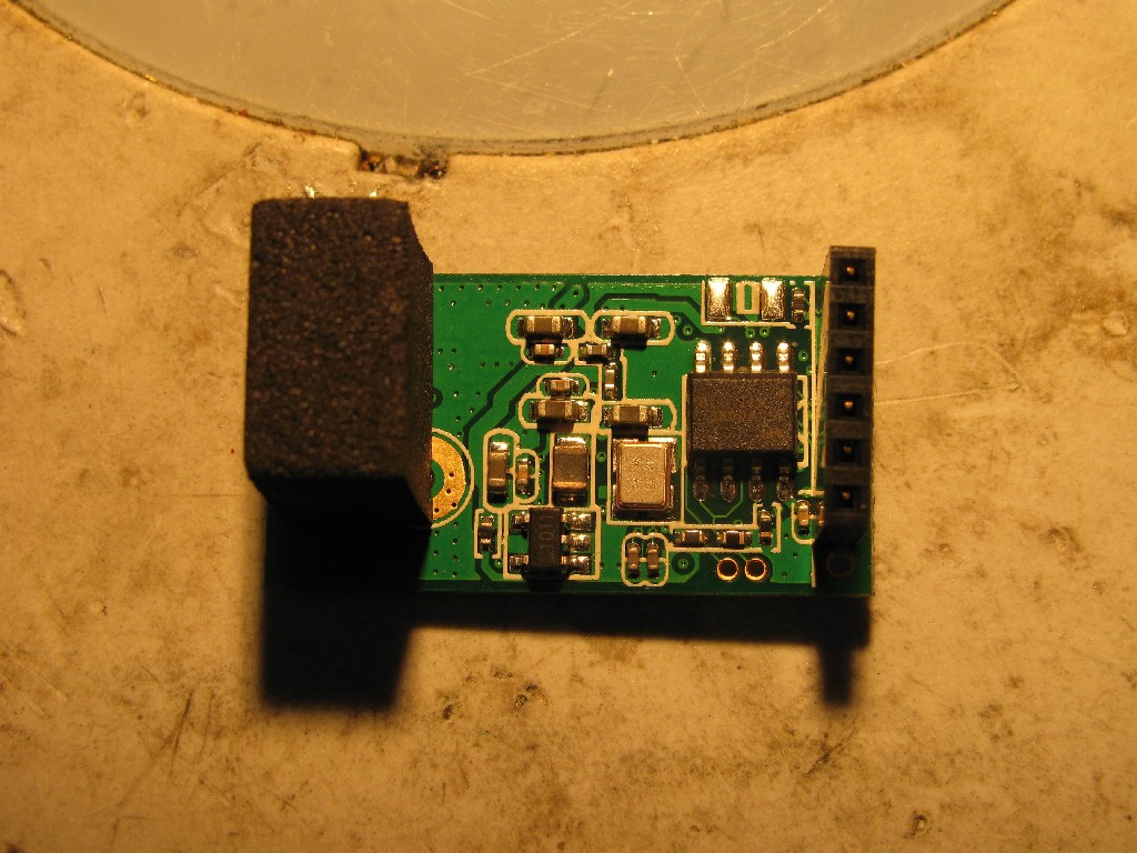
raweThe device consists of a red main board and a green wifi addon board:
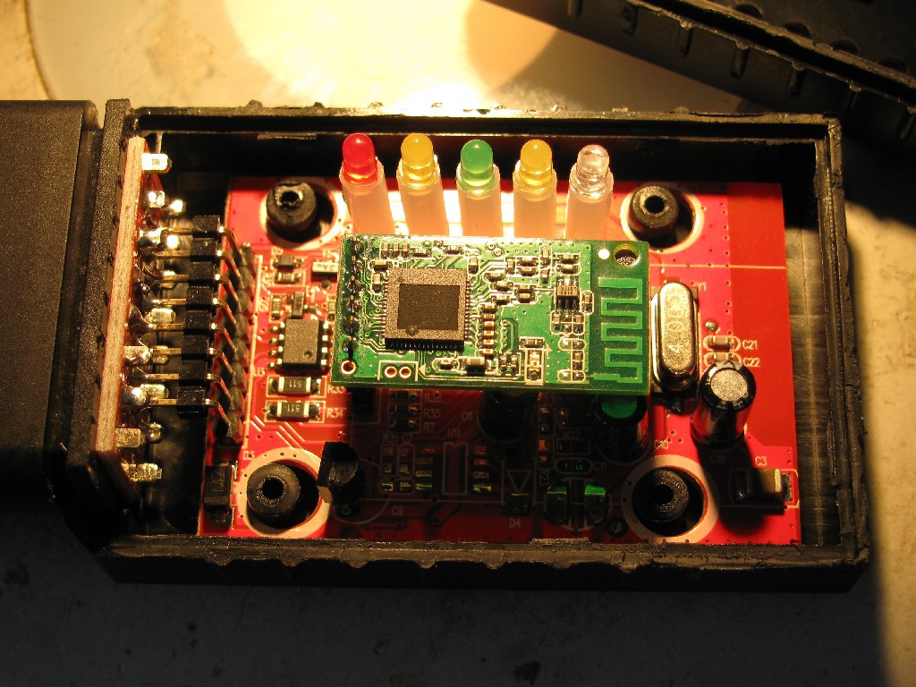
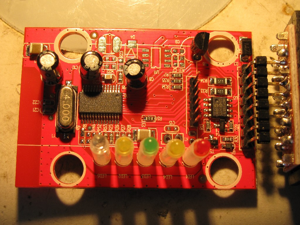
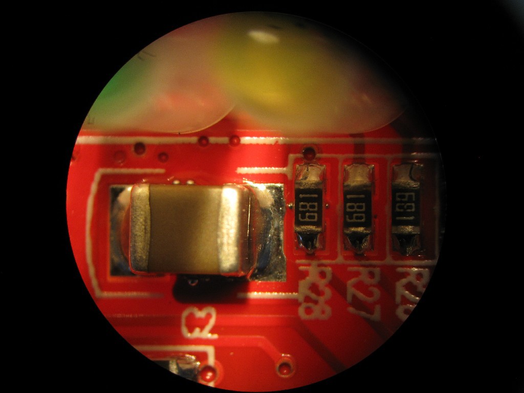
The three electrolytic caps are all 16V rated and on "car +", +5V and +3V3 rails. The chip near the conenctor is a Microchip can controller, the chip on the left is a Microchip pic 18F, which does the CAN-UART translation in the same way as the "original" ELM327 would do. UART is exposed on the pin header in the center to go to the wifi board. The unpopulated parts on the top edge of the board (SO8 IC U11, diode D4, and inductor L1) form a step-down buck converter... but they populated the lm7805 - d'oh!
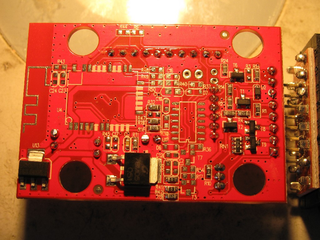
Not much on the bottom layer: 7805 and 3V3 linear (!!!) regulators and a footprint for a bluetooth module (not populated):
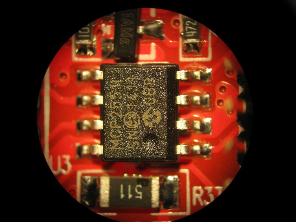
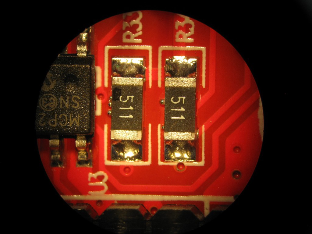
Can transceiver: MCP2551I
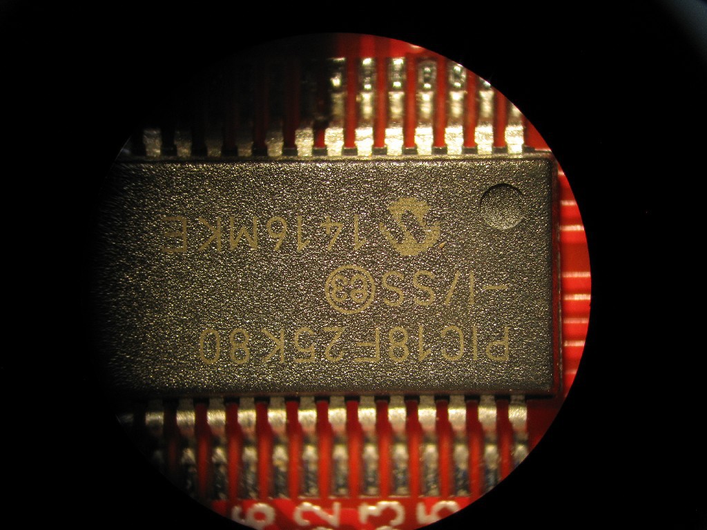
PIC microcontroller: PIC18F25K80, supported by PicKit3
The solder job is ok, except solder balls all over the place:
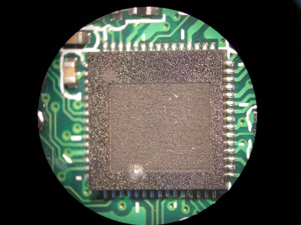
The Wifi-module consists of just one big SoC (part name removed :( ), passive differential-to-single-ended convertion circuit and a TX/RX switch for RF stuff. Footprints for PI filter is present, but not used.
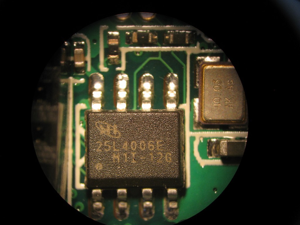
On the bottom layer, a 4Mbit SPI flash holds the software (interface pins exposed :) ), a quatz drives the clock and a LDO (?) does additional local voltage regulation. A pad to mount an U.FL connector (or similar) is present, but would need a resistor on the top side to be moved one pad.
SPI 4MBit flash: 25L4006E
Wifi SoC: unknown type, 60pins (T)QFP package
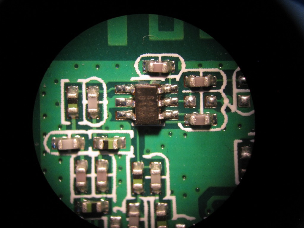
TX/RX switch (right to antenna, left/bottom are TX/RX paths)
Next step is to clean up the red main board and remove the loose solder balls, then power it up using a lab PSU and begin probing/hacking
Discussions
Become a Hackaday.io Member
Create an account to leave a comment. Already have an account? Log In.
hi, tell me pls is it possible to replace the wifi module by a ESP8266 based WiFi module?
What is the configration I need to do for setup the ESP8266 for it can transmit, and receive data on OBD2 inteerface?
Thanks.
Are you sure? yes | no
It should be possible to wire up the signals (GND, power, TX,RX, ..) to an ESP8266 board and talk to OBD2. You just need to send/receive on UART of ESP8266, see https://en.wikipedia.org/wiki/ELM327 ; http://www.elmelectronics.com/obdic.html#ELM327
Are you sure? yes | no