 deʃhipu
After a bit of research and experimenting, I can now conclude that my initial PCB design has a number of flaws, namely:
- I choose the only pin that can't be used as button when SPI is enabled, BCM7, for the UP button.
- I choose the pin that LiPO Zero module uses for signalling shutdown for the L1 button.
- I power the OLED from the regulated 3.3V, instead of the 5V power.
- I drive the mini-speakers directly from the PWM pins (with low-pass filters), without any amplifier.
- I didn't include a footprint for an ON/OFF switch.
- I placed one of the audio circuits right under the display's power coil.
- I arranged the SMD buttons in such a way, that they have to be soldered manually in a certain order.
I decided to fix those flaws in a second revision of the PCB, and in also to add an EEPROM chip that will store the pin configuration and the device tree overlays necessary to use this board. In other words, I'm turning this into a proper HAT.
Here's the second version of the PCB so far:
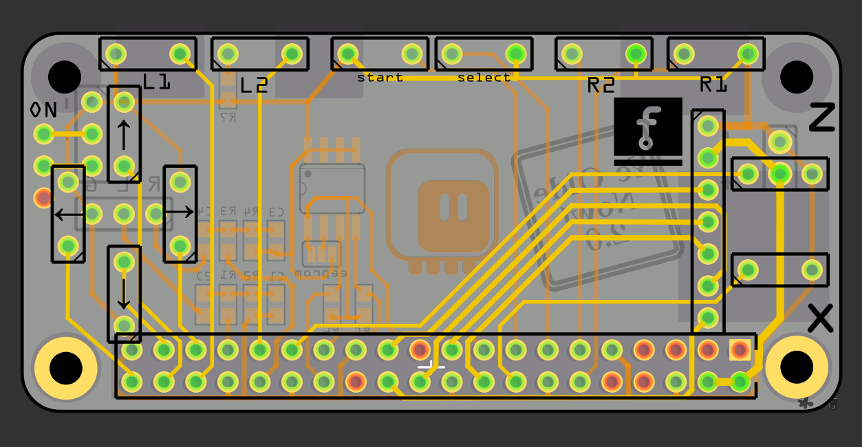
You can see that I moved the audio filters, so that they are together, and there is a header for their output -- that's where the amplifier board will go. There are no footprints for the speakers -- they will also go on the amplifier board. There is a resistor next to the L2 button, because the BCM6 pin can go high on the old Raspberry Pi versions during the boot, and we don't want to have a short when the user happens to be holding that button down. There is an EEPROM chip with its pull-up resistors for I2C, as specified in the HAT design guide. Oh, and I switched to using through-hole buttons, because they actually use less space on the board, and will be easier to solder.
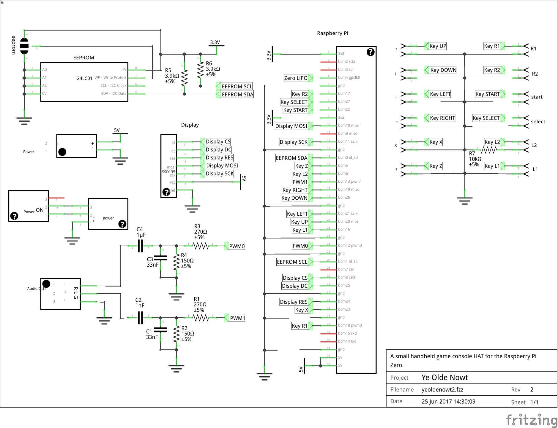
I also took the time to actually draw a proper schematic:
Then I wrote the overlay file for this board, which goes something like this:
/dts-v1/;
/plugin/;

/ {
    compatible = "brcm,bcm2835", "brcm,bcm2708", "brcm,bcm2709";

    fragment@0 {
        target = <&gpio>;
        __overlay__ {
            pinctrl-names = "default";
            pinctrl-0 = <&pwm_audio_pins>;

            pwm_audio_pins: pwm_audio_pins {
                brcm,pins = <12 13>;   // gpio no ('BCM' number)
                brcm,function = <4 4>; // 0:in, 1:out, 2: alt5, 3: alt4, 4: alt0, 5: alt1, 6: alt2, 7: alt3
                brcm,pull = <0 0>;     // 2:up 1:down 0:none
            };
            keypad_pins: keypad_pins {
                brcm,pins =     <20 26 21 19  5 23 18 17 16  6 22 27>;
                brcm,function = < 0  0  0  0  0  0  0  0  0  0  0  0>; // in
                brcm,pull =     < 2  2  2  2  2  2  2  2  2  2  2  2>; // up
            };
            oled_pins: oled_pins {
                brcm,pins = <24 25>;
                brcm,function = <1 1>;
                brcm,pull = <0 0>;
            };
        };
    };

    fragment@1 {
        target = <&soc>;
        __overlay__ {
            keypad: keypad {
                compatible = "gpio-keys";
                pinctrl-names = "default";
                pinctrl-0 = <&keypad_pins>;
                #address-cells = <1>;
                #size-cells = <0>;

                button@20 {
                    label = "up";
                    linux,code = <103>; // KEY_UP
                    gpios = <&gpio 20 1>;
                };
                button@26 {
                    label = "down";
                    linux,code = <108>; // KEY_DOWN
                    gpios = <&gpio 26 1>;
                };
                button@21 {
                    label = "left";
                    linux,code = <105>; // KEY_LEFT
                    gpios = <&gpio 21 1>;
                };
                button@19 {
                    label = "right";
                    linux,code = <106>; // KEY_RIGHT
                    gpios = <&gpio 19 1>;
                };
                button@5 {
                    label = "X";
                    linux,code = <45>; // KEY_X
                    gpios = <&gpio 5 1>;
                };
                button@23 {
                    label = "Z";
                    linux,code = <44>; // KEY_Z
                    gpios = <&gpio 23 1>;
                };
                button@18 {
                    label = "R1";
                    linux,code = <30>; // KEY_A
                    gpios = <&gpio 18 1>;
                };
                button@17 {
                    label = "R2";
                    linux,code = <31>; // KEY_S
                    gpios = <&gpio 17 1>;
                };
                button@16 {
                    label = "L1";
                    linux,code = <32>; // KEY_D
                    gpios = <&gpio 16 1>;
                };
                button@6 {
                    label = "L2";
                    linux,code = <33>; // KEY_F
                    gpios = <&gpio 6 1>;
                };
                button@22 {
                    label = "start";
                    linux,code = <28>; // KEY_ENTER
                    gpios = <&gpio 22 1>;
                };
                button@27 {
                    label = "select";
                    linux,code = <57>; // KEY_SPACE
                    gpios = <&gpio 27 1>;
                };
            };
        };
    };


    fragment@2 {
        target = <&spi0>;
        __overlay__ {
            status = "okay";
            #address-cells = <1>;
            #size-cells = <0>;

            spidev@0{
                status = "disabled";
            };
            spidev@1{
                status = "disabled";
            };
            oled_display: oled_display@0{
                compatible = "ssd,fb_ssd1351";
                status = "okay";
                reg = <0>;
                pinctrl-names = "default";
                pinctrl-0 = <&oled_pins>;

                spi-max-frequency = <20000000>;
                txbuflen = <32768>;
                rotate = <0>;
                fps = <33>;
                buswidth = <8>;
                dc-gpios = <&gpio 25 0>;
                reset-gpios = <&gpio 24 0>;
                debug = <0>;
            };
        };
    };
};
and then I tested that all of the buttons actually work properly:
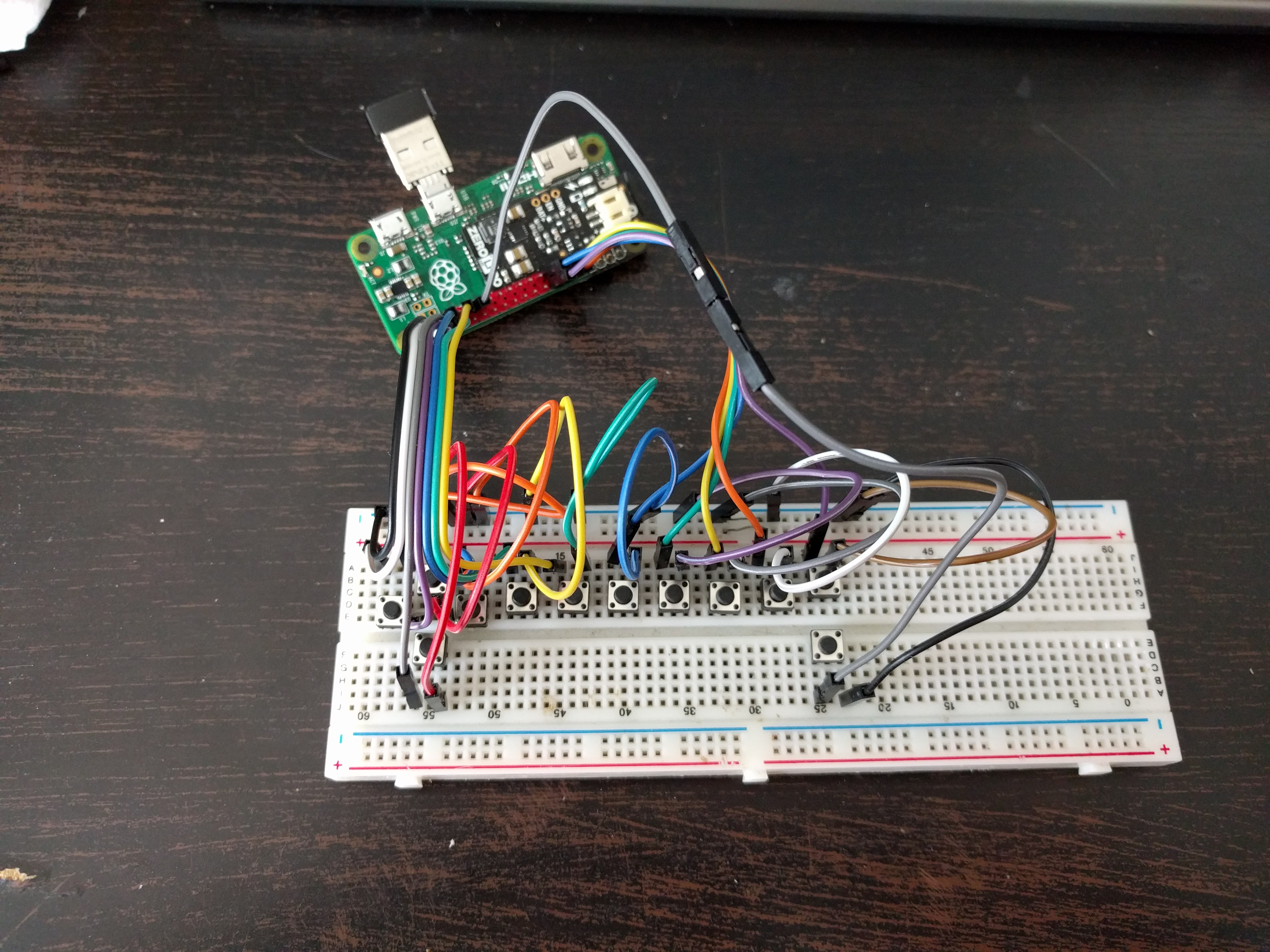
Turns out that it mostly all works, but I have to manually enable pull-ups on all the pins -- for some reason the above overlay doesn't enable them. Which is fine by me, because the EEPROM lets me do that separately, and in the worst case I will add a script that will enable them at startup.
In the end, it all turned out to be more complex than I anticipated, but I think I got it all resolved now.
Discussions
Become a Hackaday.io Member
Create an account to leave a comment. Already have an account? Log In.