 polyfractal
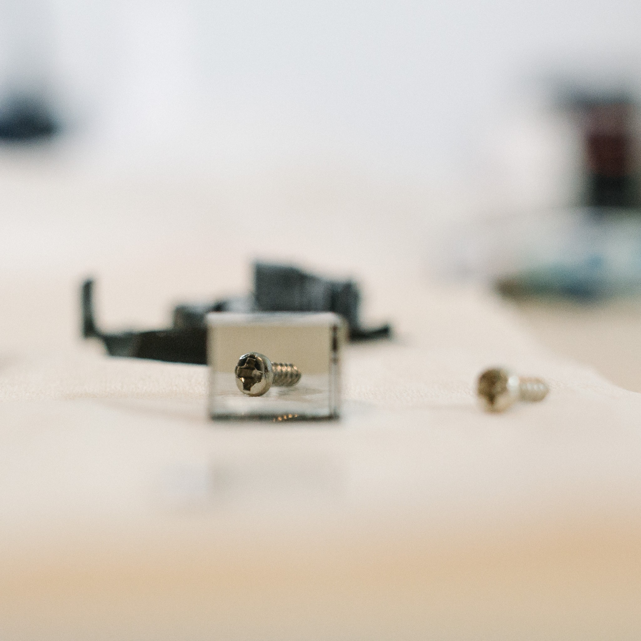
Welp. The deed is done; the final components of the light engine have been removed and measured... and the housing was destroyed in the process.
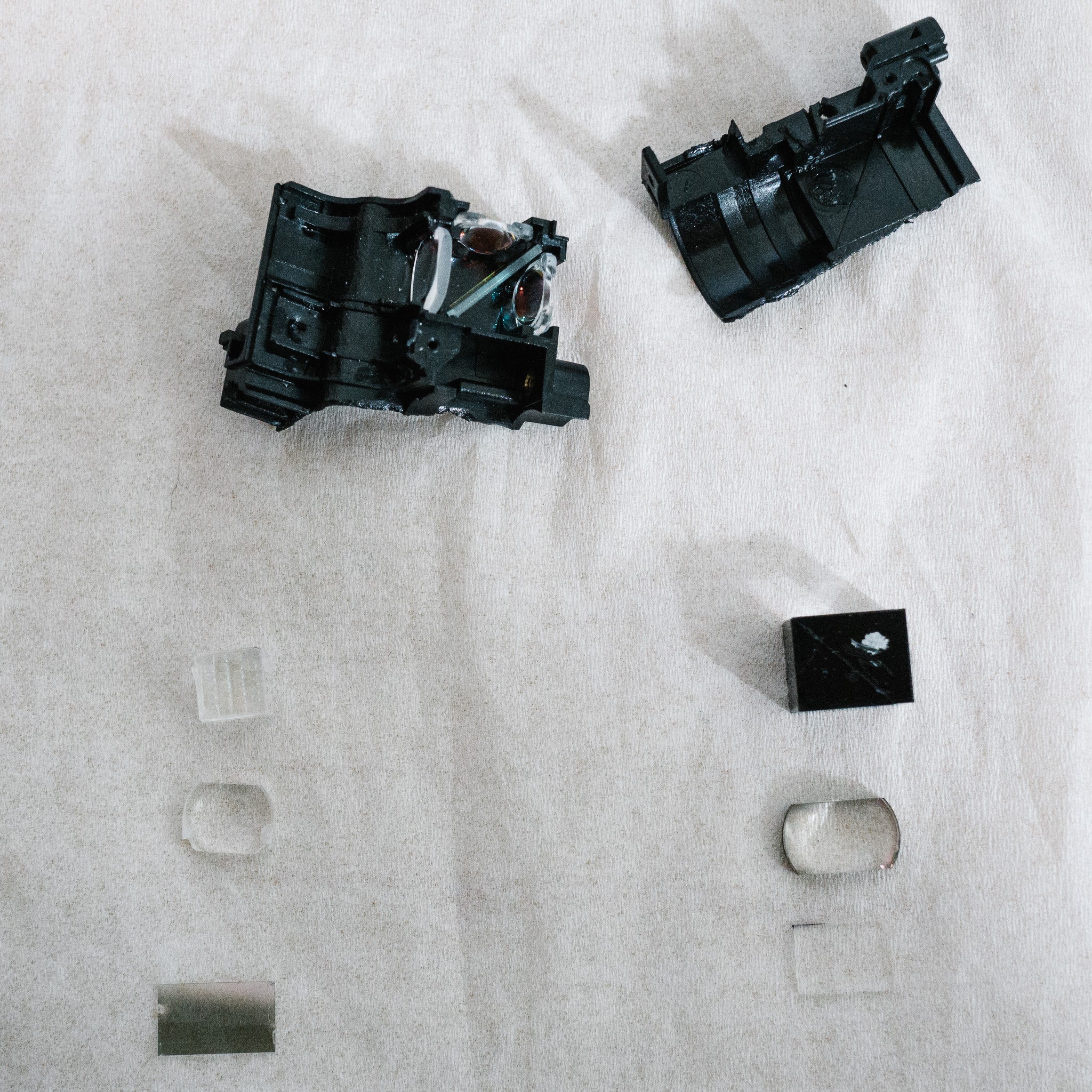
After removing and measuring the components, I started playing around with them and discovered a few interesting, unexpected things.
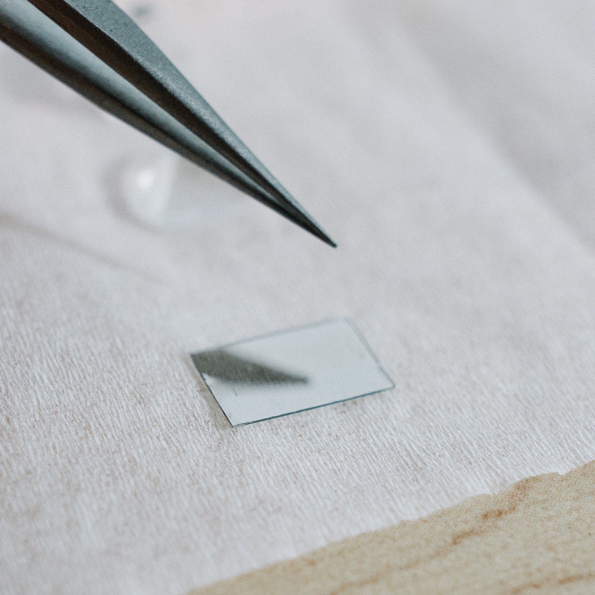
Two of the components -- the thin plastic filter on the left and the glass plate on the right -- are not exactly what I thought they were. I assumed they were both polarizers. As it turns out, the plastic filter is partially silvered:
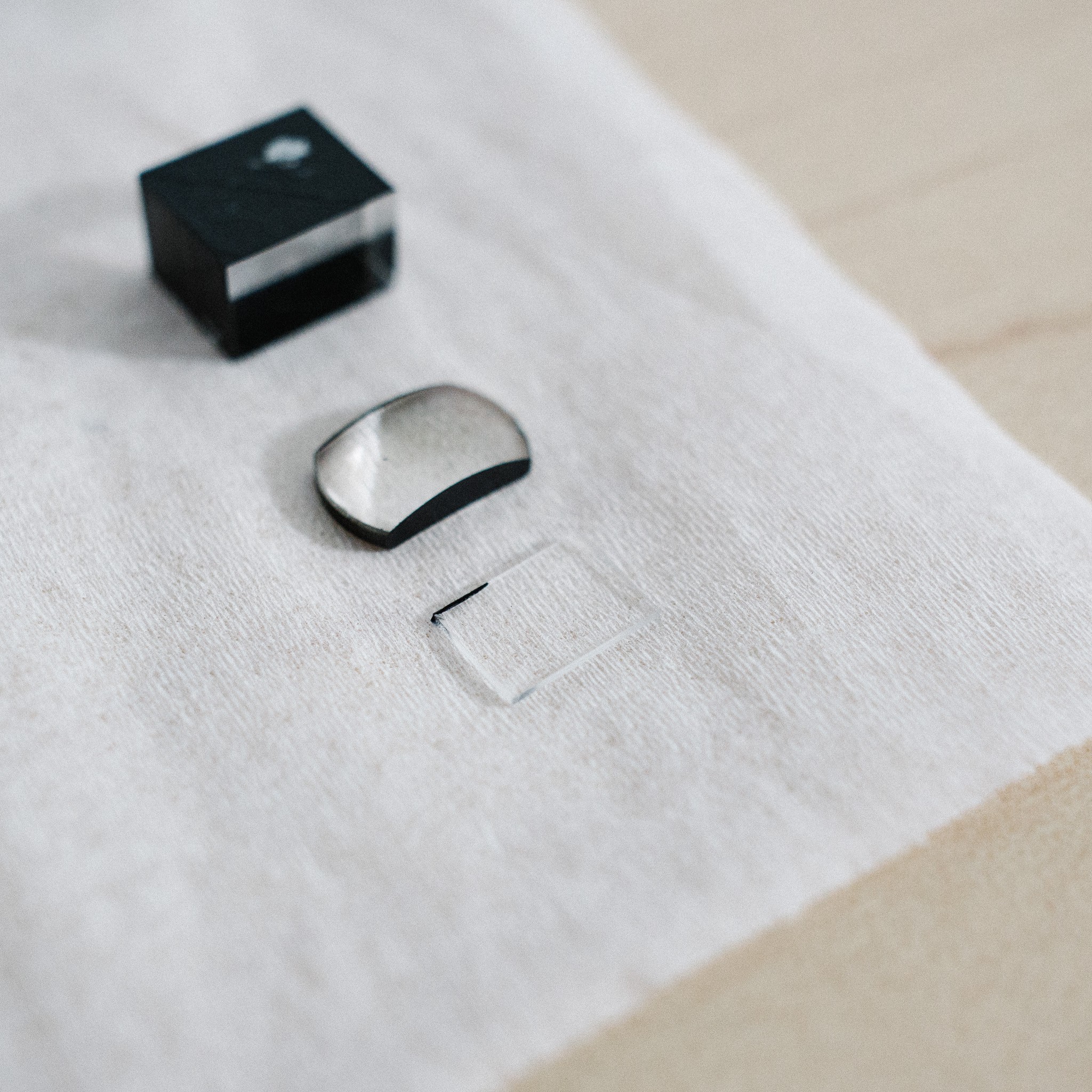
And the glass plate looks absolutely transparent to me, no noticeable effect:
While playing around with the components on my desk, I noticed that the stack only really worked well with both filters in place (although the lenses appear, thankfully, optional and just for projection). With the filters removed I could see some laser light through the splitter, but not much. When plates were in place, the contrast was better.
So what's going on?
After some research, it appears that my understanding of LCoS displays was subtly incorrect. I knew that LCD technology relies on polarization to make pixels visible. Two polarizers on the front and back of the LCD prevent any light from exiting the device. But when a liquid crystal cell twists due to electrical stimulation, the twist polarizes the light so it can escape the second polarizer. Varying the amount of twist allows different gray-levels.
I assumed LCoS worked the same. They do, in a fashion, but the reflective nature of LCoS chips means the setup is a little different.
I found a website dedicated to projectors which helps explain how an LCoS works. Single-chip LCoS like mine look like this:
The "S" and "P" represent two different polarization states of the light. "PBS" stands for "polarized beam splitter", which is basically a beamsplitter that reflects one polarization of light ("S" in this image) and transmits the other ("P").
The device works like this. The light source blasts out randomly polarized light (or can be pre-filtered to a certain polarization). One orientation reflects off the PBS, shoots through an "off" pixel on the LCoS, then hits the reflective layer below. Because it is being reflected directly, the polarization doesn't change, so it is reflected again by the PBS back into the light source:
 But when voltage is applied to a pixel, the liquid crystals shift. The light that is reflected off the PBS twists through these crystals and alter the polarization from S to P. This new orientation is now transmitted through the PBS instead of being reflected, so the "on" pixel is sent out through the projection lens:
 Neat! So that explains the overall setup, but it doesn't quite explain the two filters and their purpose.
Let's tackle the clear glass filter first. While researching, I found this passage (from D-ILA™ Projector Technology: The Path to High Resolution Projection Displays ):
To improve the contrast ratio of the PBS a nominal quarter wave plate retarder is inserted between the PBS and the D-ILA
Hmm. Not much to go on, but enough to start digging. After sifting through some more sources, I found this quote in Projection Displays (emphasis mine):
Another problem with a polarizing beam splitter in a reflective LCD system is that the PBS, even with auxiliary pre- and post-polarizers, may limit the maximum contrast the system can achieve. This can occur if the PBS mixes polarization states, and converts some horizontally polarized light into vertically polarized light or vice versa. […]
Correction of this problem involves the insertion of a quarter-wave plate between the PBS and the LCoS imager. Sophisticated, wavelength and angle independent quarter-wave plates can be used but even a single layer wave plate can increase the contrast by a factor of 10.
So there we go. It appears likely that the glass plate is a quarter-wave plate, with the purpose of cleaning up any stray orientations that make it through the PBS. That would explain why everything worked without it in place...but worked better when added back to the stack.
But what about that silvered plastic filter? It could be a pre-polarizer, which is mentioned in multiple sources and nicely illustrated in Projection Displays:
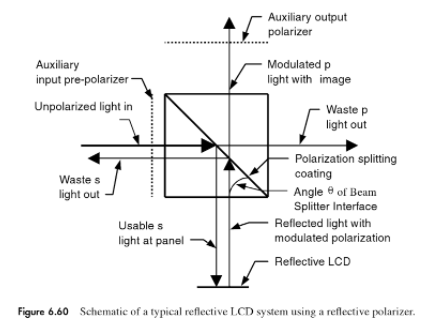
But I don't think that's it, namely because I don't think polarizers are silvered in appearance. The quarter-wave plate is clear, and the circular/linear polarizers that I have laying around my parts bin are all variations of clear/smoky. None are silvered.
I think the plastic filter is just there to collect waste light that is being reflected by the PBS and redirect it back into the splitter. The LEDs that drive the assembly don't have any reflectors attached, and so it would make sense to collect some of the waste light. The best place to do it is right after the beams have been collimated together, before the PBS, rather than at each individual LED.
I'm not 100% on that, but it seems reasonable.
So moving forward, it looks like I'll be keeping the two filters, but ditching the PCX lenses. I really wasn't expecting the setup to be quite so complex, but it was a fun diversion into learning more optics :)
Hopefully next update will be about the final printed enclosure :)
Discussions
Become a Hackaday.io Member
Create an account to leave a comment. Already have an account? Log In.