 polyfractal
I pulled apart the various components and tested them individually, and I'm fairly convinced the problem is the polarizing beam splitter. If I replace the LCoS with a simple mirror and remove all the other components, I see this:
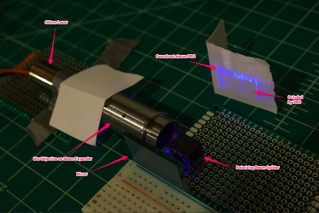
Tl;dr: not good news. :/
It appears tha the beam is occluded by the PBS, which means it is doing its job blocking the incorrectly polarized light. BUT, as you can see in the image, there is some "overshoot" because my beam isn't perfectly collimated. It slowly diverges, which means some of the light is passing through the splitter on the way in...but then diverges enough that it passes above the splitter on the way back.
That overshoot shows the problematic pattern. I can't think of any way this is being generated unless it was the splitter material itself. And it becomes visible when the LCoS is in place because the light polarizes correctly, passes through the splitter and we see it.
(Note: it's not the laser itself, I checked to make sure the beam was relatively uniform).
I also asked on Stack Overflow, which introduces another potential problem I didn't think about Quoting the answer I received:
My guess is that there are multiple things at the same time, which include the ones you mention. But probably the most fundamental one (I dealt with it once) is that your reflective pixels are in matrix which acts as a diffraction grating. Even if the size of the single pixel is larger than the wavelength (several tens of microns Vs 400 nm), the pixels and the opaque space between them have sharp edges, regularly distributed. So with monochromatic light you'll get the diffraction from that. One way out of it is to spatially filter the light, with some redesign: a pinhole between two positive lenses, before the objective.
I imagine this is also contributing to the problem, making any potential noise even worse.
Time to change tactics?
So, that sucks. Need to think about next steps.
I'm strongly tempted to shelve the LCoS and just build a simple Direct Write Lithography setup (DWL). In this configuration, a simple optical stack (e.g. a microscope objective) is used to focus a laser to a diffraction-limited point. Then the substrate or laser is then physically moved around.
Basically, it's a laser etcher. Just with more precise movements and a lower power laser, but the principle is the same; it's an XY plotter.
Another option is to use laser galvos, but this introduces some non-trivial problems involving focusing the beam. The focus from laser galvos follows a spherical path, but the surface is flat. So you either need expensive f-theta "flat field" lenses to correct the spherical aberration, or build a variable focus system to adjust dynamically.
I'm kinda tired of messing with optics, so the xy plotter appeals to me.
We'll see. Updates to follow after some thinking :)
Discussions
Become a Hackaday.io Member
Create an account to leave a comment. Already have an account? Log In.
It's unfortunate that it didn't work as intended but we both learned something. However, different approaches to inexpensive high precision maskless lithography is something I've investigated for a while, so I'll share what I know.
* Spinning polygons and galvos aren't cheap (can't build them either) but they generally need fast lasers.
* The q-switched lasers are fast and they are always going to be expensive.
* Voice Coil Actuators can be constructed (need to build a coil winding machine) and they are ideal but friction from moving the stage reduces your resolution.
* You can eliminate friction by using magnetic levitation but it will reduce your vertical accuracy.
* A stage moved by maglev VCA can be used to move the wafer on the X axis while a second separate stage can be used to move optics and a small laser (e.g. from blu-ray drive) on the Y axis.
* A MEMS camera lens focus can be used to adjust the optics for the laser once you figure out the calibration settings needed for positions along each axis.
You can follow the maglev VCA idea or try to figure out how to make a galvo/spinning polygon do your bidding at a low speed for a "slow" laser and proceed from there.
Are you sure? yes | no
This is awesome, thanks! Echoes a lot of what I was thinking regarding VCA.
Why can't galvos be built? They look fairly straightforward if you're willing to accept modest resolution
Out of curiosity, do you happen to know the switching speed of diode lasers? I was assuming they were pretty similar to LED switching speed (few Mhz)?
Are you sure? yes | no
Galvos and spinning polygons need perfectly flat reflectors to be of any real use. This means you have to buy the reflector which is generally expensive... unless you plan on making a machine to level the surface. I suppose you could calibrate for the inconsistencies in the surface too but I get the feeling it's more trouble than it's worth.
I'm not 100% but I think I saw a datasheet that showed they stay on for several microseconds once activated. You would really need to look at the datasheet of whoever you buy one from.
I suggest going with making a maglev sled with a magnet on one end that will slide in and out of a voice coil without ever touching. I'd make it myself but I'm shit with 3d modeling and analog circuits. :)
Are you sure? yes | no
@Gravis Ah, gotcha. Yeah I definitely don't have the tools or skill to machine my own reflectors :) If I went that route, my plan was to get some small λ/4 first surface mirrors from Edmunds or similar. They aren't too pricey ($10-40, depending on coating). That's probably good enough for my purposes, and higher precision mirrors do indeed get expensive fast :)
Are you sure? yes | no
[this comment has been deleted]
It's definitely an option! Thanks for the suggestion, a laser printer didn't even occur to me :)
I think it has similar considerations as the galvo setup; namely that the focal length changes as it sweeps across the axis.
I think it would probably give better resolution that a galvo setup though. A galvo has limited travel, maybe 20 degrees. So even a high-resolution encoder + geared micromotor (20k pulses per rotation) only gives ~1100 pulses for 20 degrees. A voice coil or something may be better control, not sure.
But a spinning polygon mirror's resolution is really only limited by how quickly you can switch the laser because the polygon's movement is (theoretically) constant. Still need a mechanical feed for the x-axis. But as you said, a lot of the components would be easily obtained.
Hmm.... adding to the list to think about :)
Are you sure? yes | no
@Cyberman Yeah, spherical focal plane basically means the overall feature size has to be larger at the edges. Or limiting the size of the "die", to limit the amount of spherical aberration. But that's probably fine, it's not like I'm trying to compete with Intel :)
Agreeing re: DPI... that's probably a limitation of the toner and paper properties rather than the laser.
I'm in North America :)
Are you sure? yes | no
@Cyberman ++ I think this is the route I'm going to try first. I have some of the components already, namely some 1000:1 brushed micromotors with encoders, giving 20k pulses per rotation. Will take a little more software to drive than a standard stepper but not too bad.
I'm investigating if I can get some research-grade xy stages for cheap on ebay. Many of those give really good resolution with minimal/no backlash. They have tiny travel ranges (like 12mm) but that should be perfectly fine for hobby die production :)
It also simplifies the optics: shoot laser into 60x objective, adjust z-axis, done.
Are you sure? yes | no
@Cyberman Actually, I already have some axis I may try out first. They are aluminum CNC axis, which are fitted with 16 turn/in threads (1587.5 microns per revolution). Coupled with some other gear motors I have with 8400 pulses/revolution, that works out to 188nm per pulse.
Which of course won't happen, given backlash, stiction and motor control problems. But even a few microns (or 10!) would be fine with me.
So yeah, I expect next update will be some kind of xy stage cobbled together :)
Are you sure? yes | no