Thomas
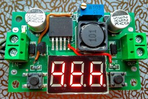
I found a new example of circuit bending grade electronics engineering in my postbox: the XH-M188.
It's advertised as "XH-M188 numerical control voltage regulation
module" and it's rated "0-12V 1.5A 18W", and first time I checked there
was exactly nothing on Google about this cheap board. Now there it is on HaD ;-) 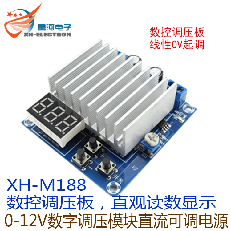
As expected the board has a STM8S003F3 µC - there was no way to know that for sure, but call it gut-feeling ;-). The GPIOs are all used for either 7S-LED, keys, or the "numerical control" (and one seems to be unconnected). We're lucky though: the LED display can be removed from the socket, exposing 11 GPIOs :-)
I did some experiments with the software that comes with the board:
- the "numerical control" is just a 4.5 kHz PWM signal with duty cycle setting through "+" and "-" key
- the control part is indeed analog (LM358 with a TIP142)
- the display value represents "duty cycle * X". There is no feedback whatsoever.
- as expected, the ratio of "display value" to "PWM duty-cycle" is constant
- the output voltage can be adjusted with the help of a trimmer potentiometer
- the LED multiplex clock is about 16xPWM cycles
Due to an apparent bug in the PMW code every 16th cycle is only about half. This leads to an output ripple with about 280 Hz, and to an offset (which can't be compensated with the trimmer). However, this inaccuracy doesn't really matter since the "voltage reference" is a LM7805.
Due to the bipolar op-amp (LM358) the maximum output voltage is 11.4 V (at the rated supply voltage of 15 V), and the accuracy drops considerable from just below 11V.
All this doesn't mean that the board is good for nothing. At $4.75 it's an inexpensive piece of lab equipment, e.g. for home-brew test automation!
Here is the current project status
- @Elliot Williams took the lead and contributed initial STM8EF board support code
- a µC pin connection list is in the project GitHub Wiki
- 11 GPIO can be used for your application without any soldering
- it's based on STM8EF, a stable self-contained programming environment
- board keys can be interpreted in background code (yes, multitasking!)
All you need for scripting is a serial terminal!
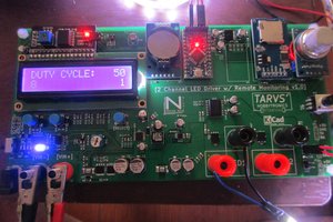
 Tim Savage
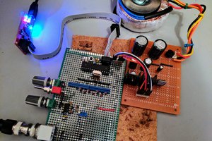
 CaptMcAllister