 David Brown
Shared under the Creative Commons - Attribution - ShareAlike 3.0 license.
The aim is to use this manipulator to position an optic fiber in front of a laser diode (when the maximum output is passing down the fiber), the fiber is then glued in position. This is how pig-tailed laser diode modules are created.
Industrially the assembly of pig-tail modules uses machines that must cost tens of thousands of dollars. These use the same layout, a Gough-Stewart platform, using six actuators to give the six degrees of freedom control.
in my case the manipulator will be manually moved so that the fiber is within a millimeter or less of the correct position and then the manipulator will make the final positioning and hold the position whilst the fiber is glued down to a support structure.
Other possible uses:
-
As a platform for supporting small samples in bio-sciences research, either inverted as a standard stage or with a modified main frame to allow the microscope to view down through the centre.
-
As a manipulator where both triangular frames are modified to allow view down through both parts, with end effector positioned into the centre of the platform.
-
With an alternate design of platform incorporating vacuum nozzle, discrete optical elements could be manipulated as required.
-
To support end of microscope fibre optic bundle to allow viewing around a specimen
The test code Git repository can be found in the links section below.
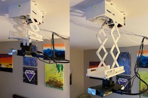
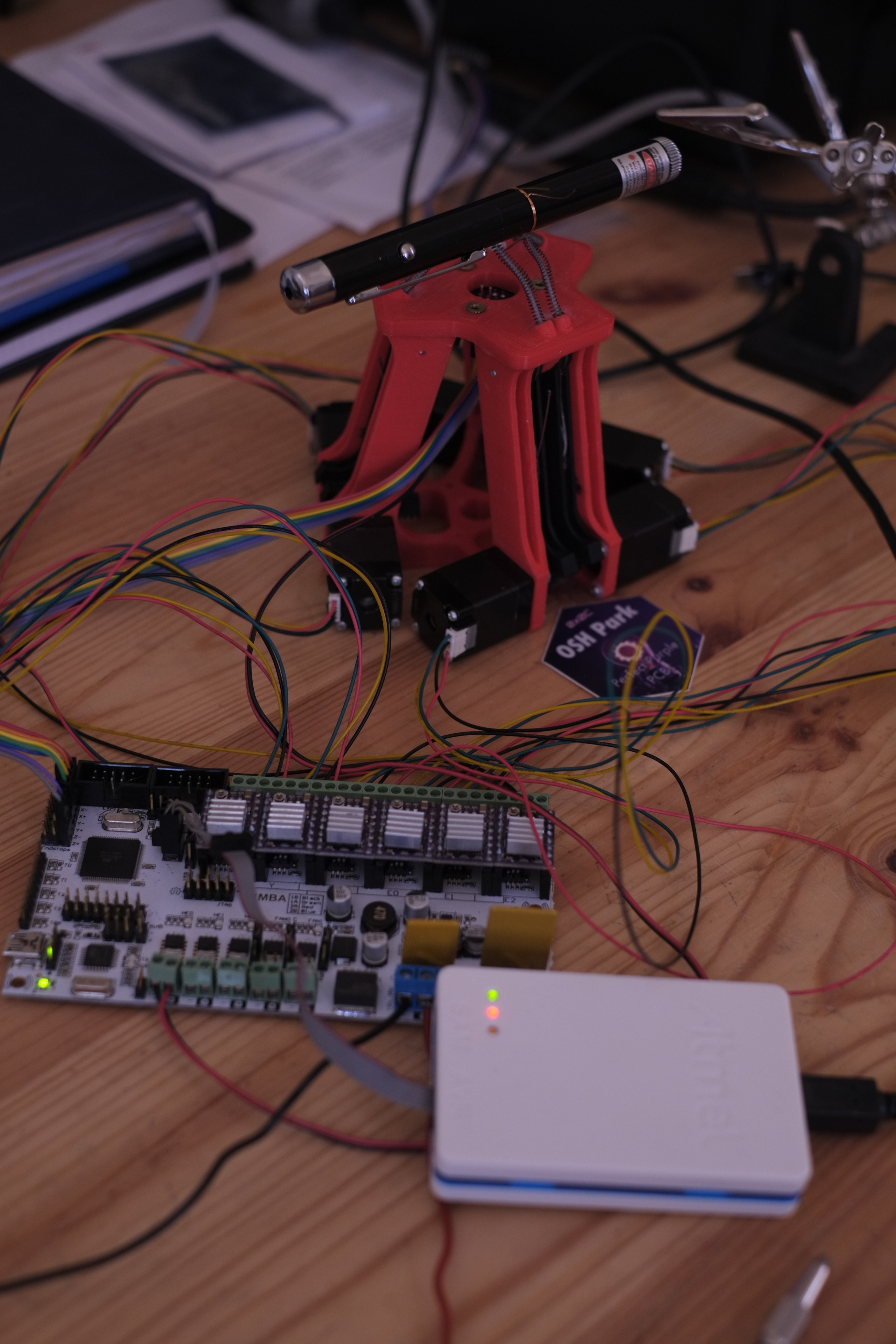 Figure; Laser pointer mounted to the platform (test rotations)
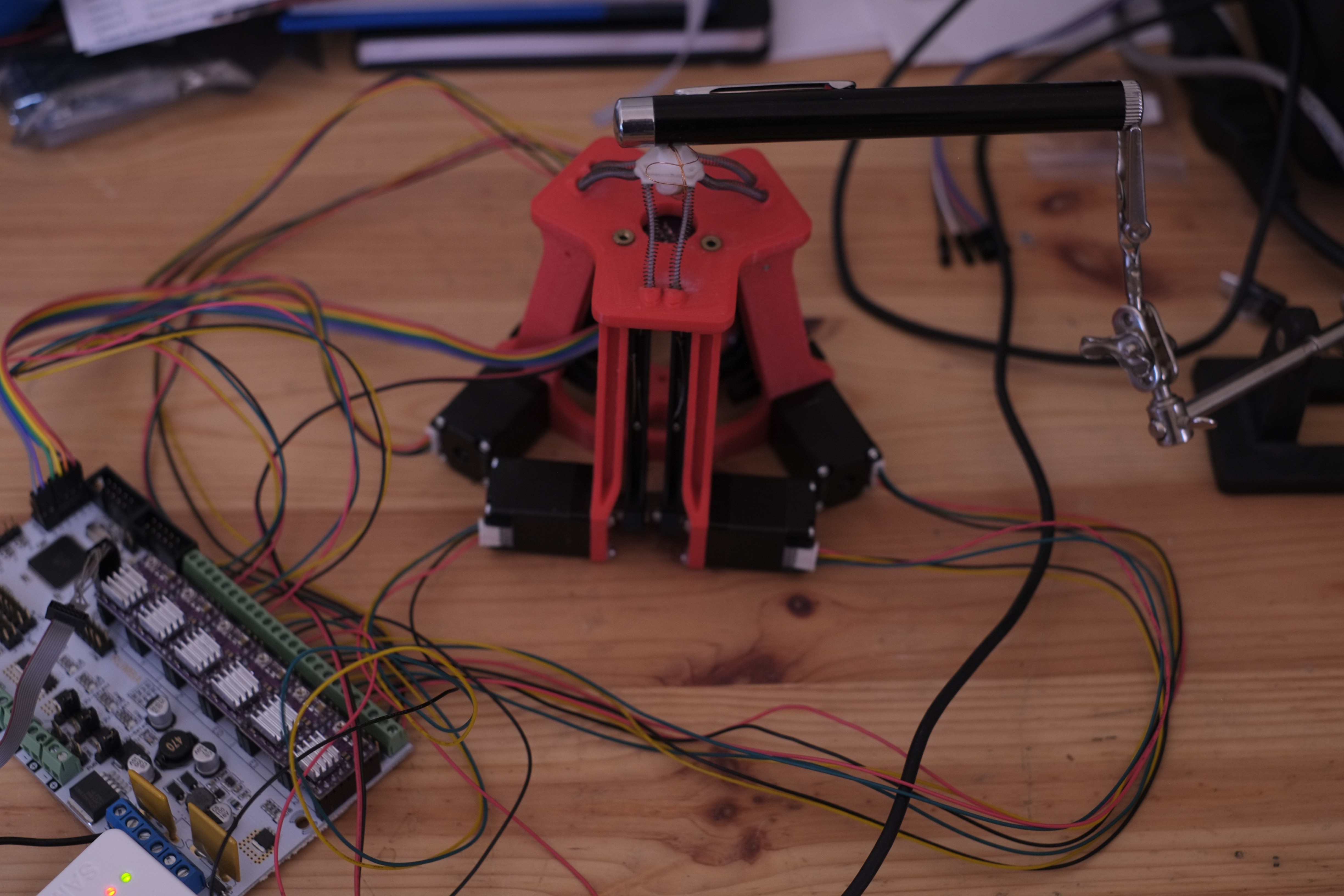 Figure; one end of the laser pointer supported (test translations)
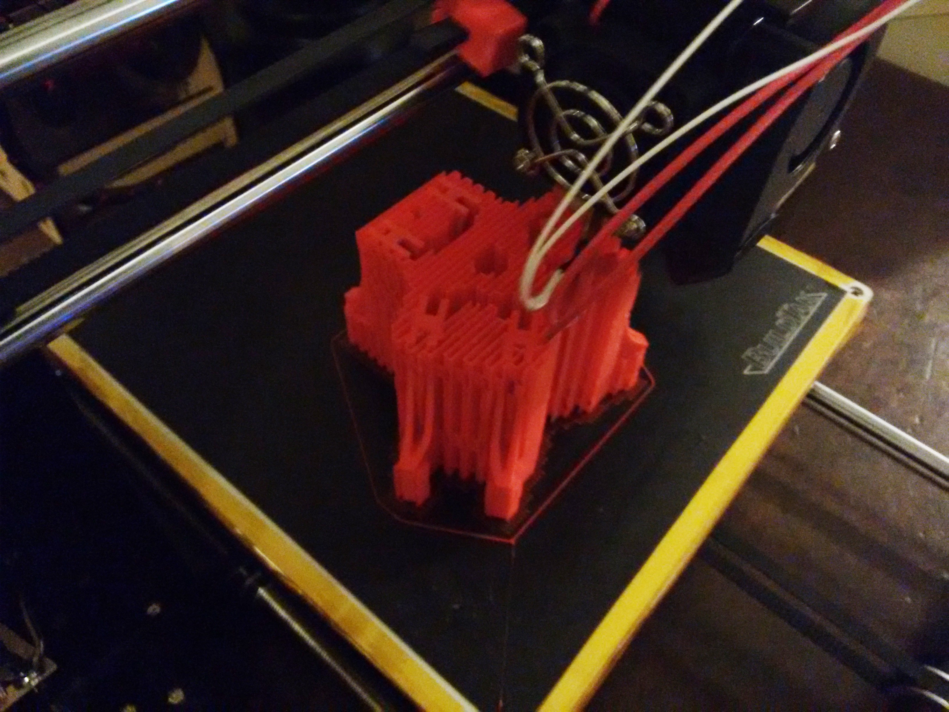 The print of the frame took 15 hours and i was pleased with the quality, given that this was using the $150 printer with all stock nozzle, etc. I'll post up the models for the parts shortly. More after break below;
 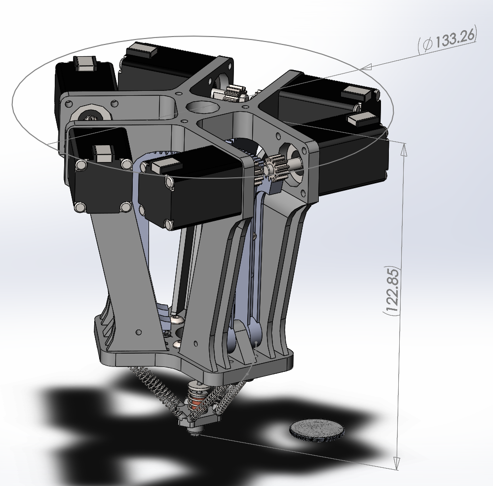 units = mm
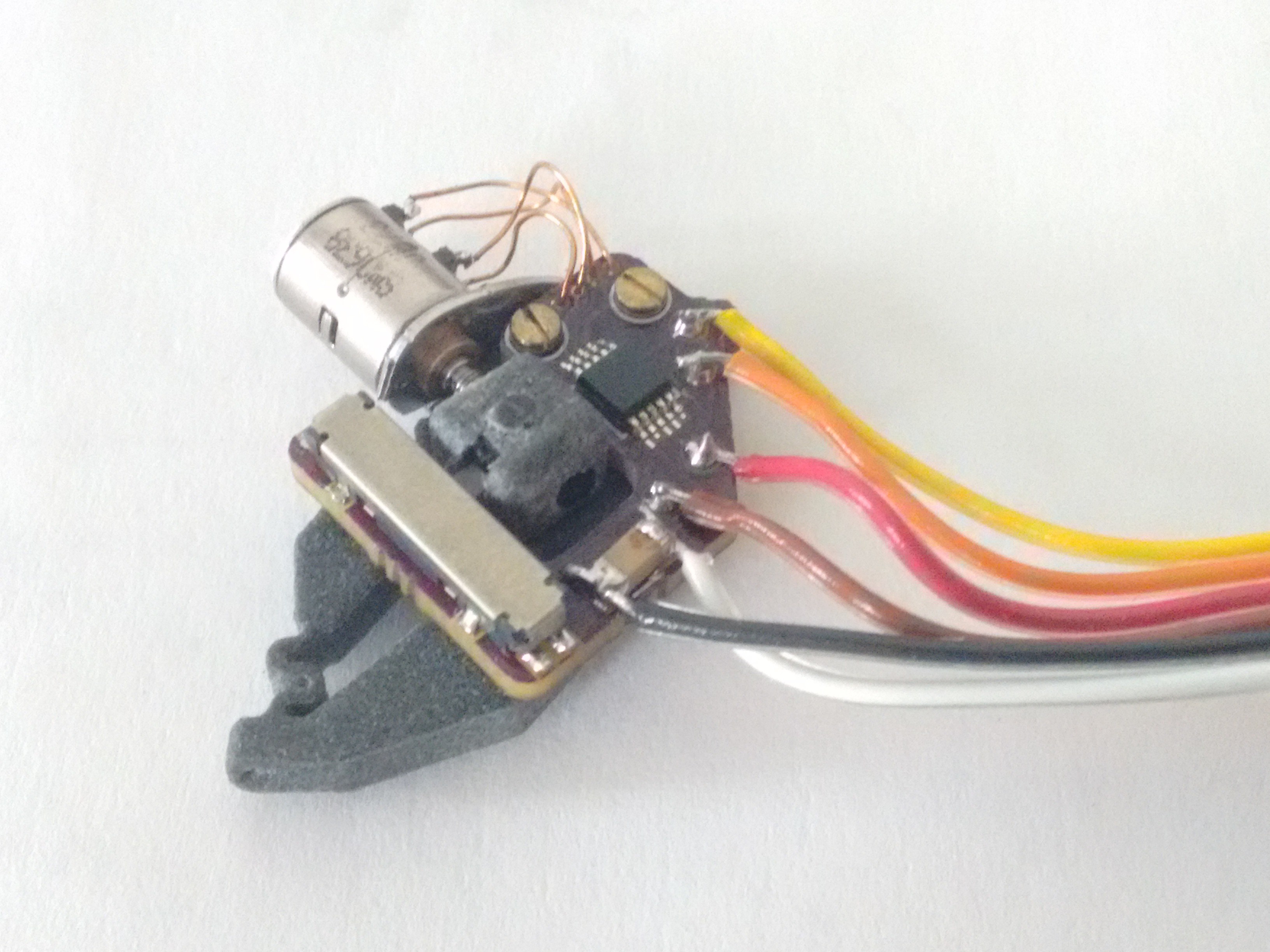
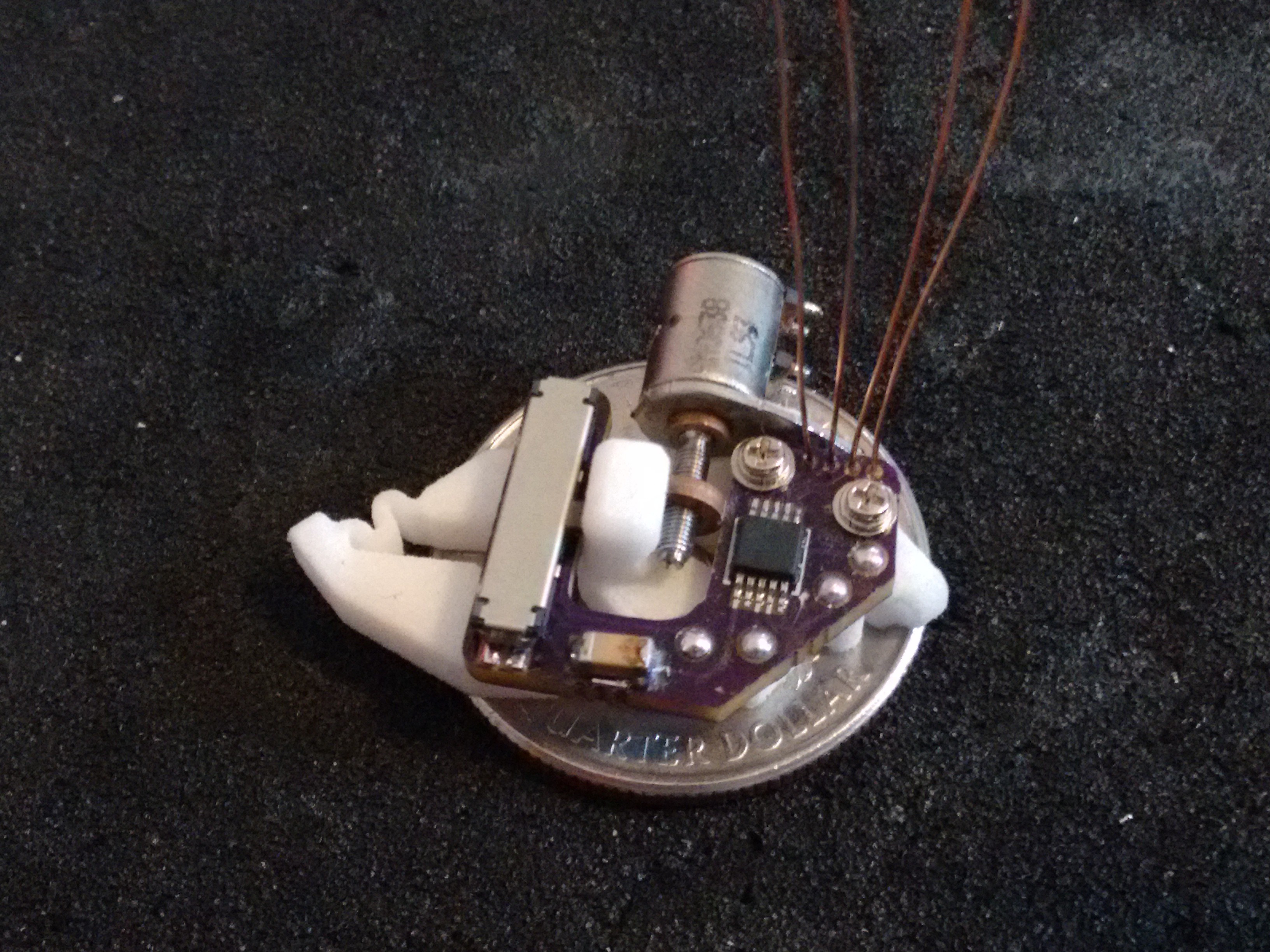
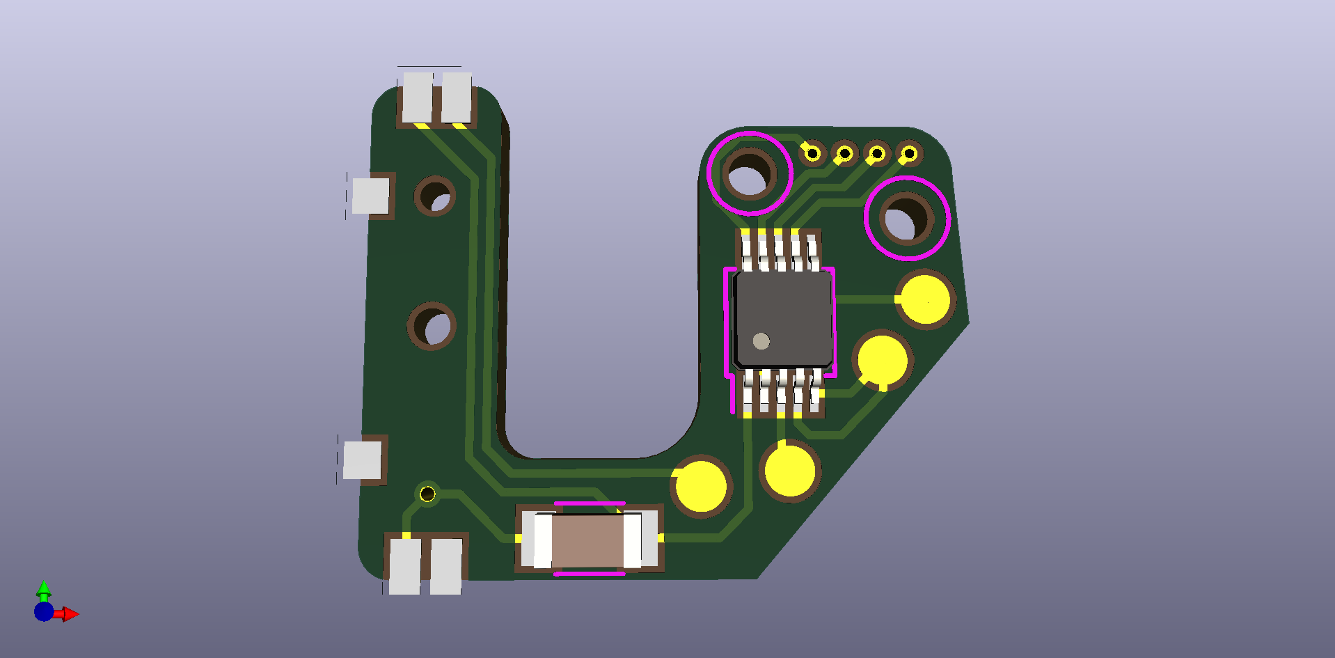 This has been designed for both the LB1935FA and LB1848MC bipolar motor control ICs, as i've still got a few pieces of the now obselete
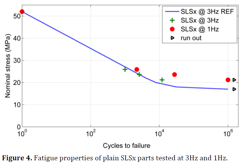 The design followed an itterative process from the initial design, extending the length of the thin hinge material. Initially simply, but when I found the fatigue


 Sam Baker
 Bree Hoffman
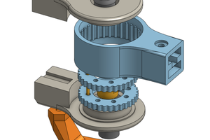
 Tim Wilkinson
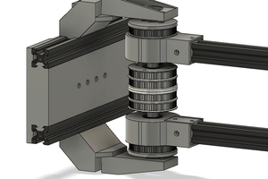
 wschneider
The actuators look they would be great for use in automated wafer alignment for semiconductor lithography. :)