David Brown
-
Design rev A2
06/20/2017 at 02:01 • 0 commentsThe alternative motors arrived, so i've been updating the design to use one of the types. The originally ordered ones arrived, but need a separate tooth part to run against the screw, so they are a no-go for this application.
![]()
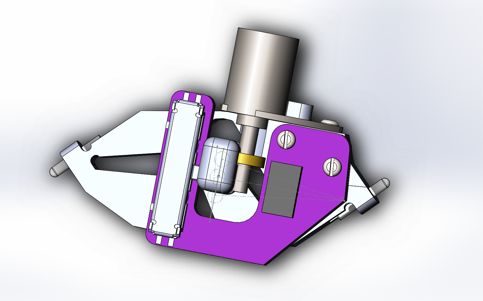
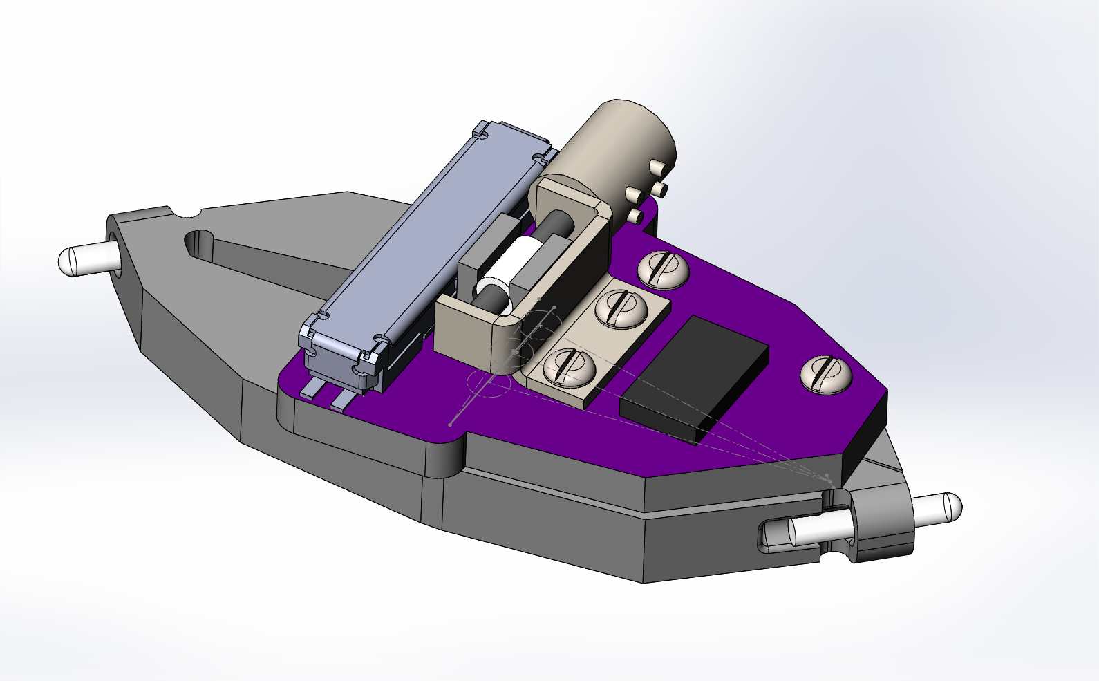
Figure: Updated actuator for alternative motor
The new motors stick out one of the sides, this required a re-design for the main frame to give them space to move, without clashing. The next step is to run some simulations of the actuator bodies to get an idea of their longevity and the forces the motor will need to apply. If too high then they will need a re-design by thinning the hinges.
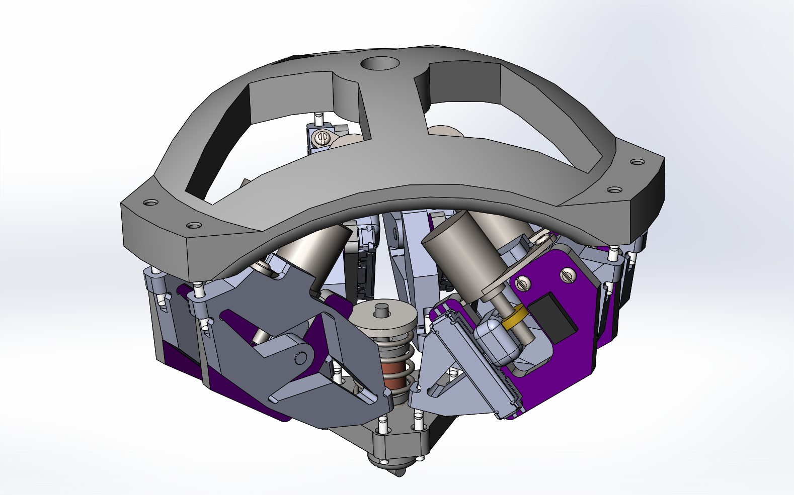
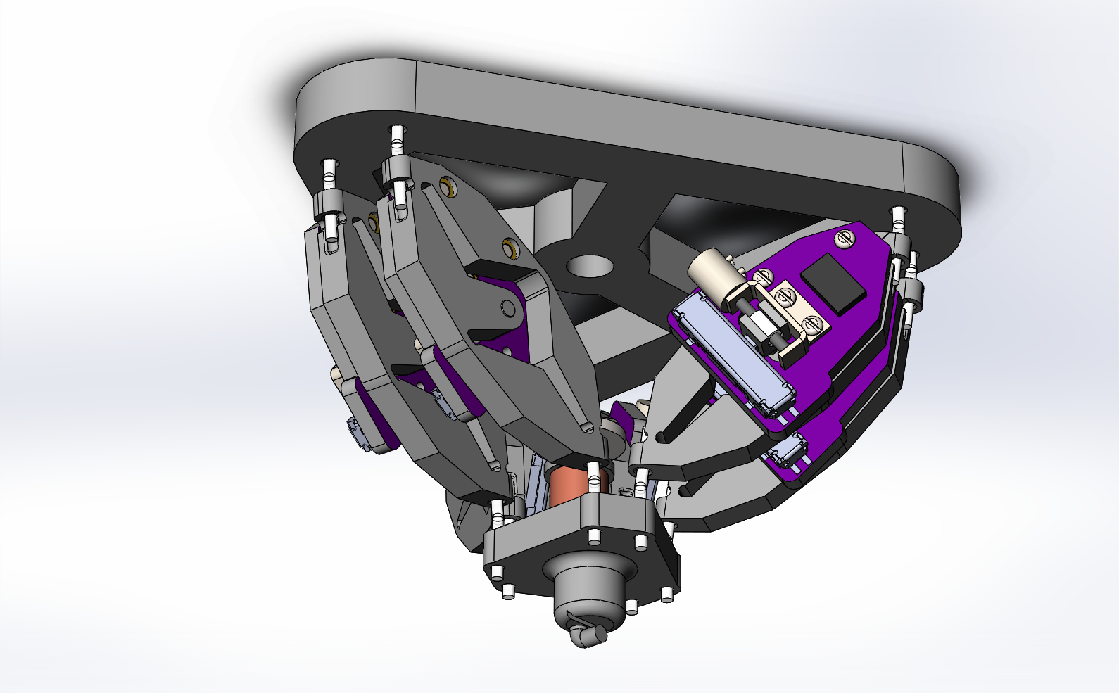
This could be done manually as there are size limits for getting the parts printed using nylon powder fusing method. The thinnest part of the joints is 0.7mm thick at the moment.![]()
Figure: Main frame updated for new actuators
I've also identified the optical fiber i will be using which has a core diameter of 105um with an outer coating diameter of 250um, so the end effector needs to be able to securly grip this diameter without damaging it.
-
Ordered some alternative motors
06/07/2017 at 15:38 • 0 commentsWith the first ordered motors in customs limbo I've ordered some alternative motors with brass nuts (which may be needed for higher forces). These will take a few weeks to come through, so I will see if i can put together some hand calculations for the forces and a finite element analysis of the fused nylon mechanism to see what the local stresses are and if there will be fatigue issues.
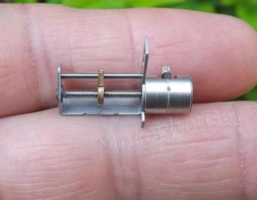
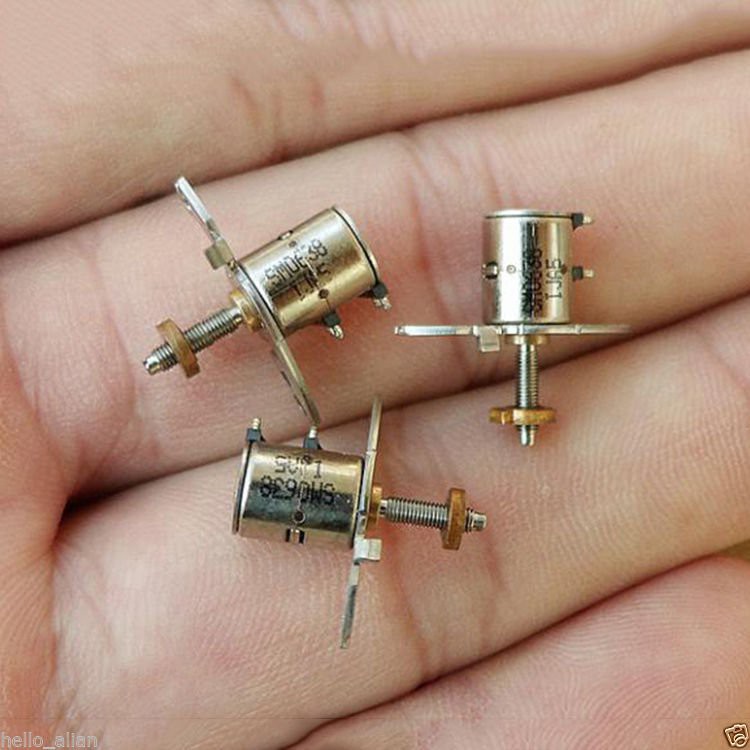
All of the motors look like they were originally for use in camera lenses. So one of the complications is working around the mounting arrangements.
![]()
![]()
-
initial update
06/06/2017 at 23:18 • 0 commentsI ordered the motors shown in the images a month ago and still waiting for them to exit customs, so have pushed on with design that can be updated when they finally arrive. They were less than a dollar for 10 including postage, you get what you pay for. I may order some others for design flexibility.
The design will use conformal joints / living hinges and use 3D printed components connected using monofilament line. This ensures that there is no backlash, which is critical for this level of resolution.
![]()
Figure - 1.8mm thick PCB provides foundation for the motor and resistor, fitted together with M1.2 screws, the micro linear resistor provides feedback to the controler. The motor driver IC will be on the board so that only lower current drive signals are in the wiring, and reduces the number of wires required.
![]()
Figure - The end effector is designed to hold an optical fiber to allow me to position when building a pig-tailed laser diode assembly.
It's hard to appreciate just how small this will be; being able to fit in a rough 40mm x 40mm x 40mm volume.
6-Axis Micro Manipulator
Micron level manipulator, using printed and low cost components