 DigiGram
Doing titrations require precise pump control. In the lab we use expensive micro syringes attached to overpriced servo's for fine control, but I think that is not necessary here. All I need is to be able to deliver drops. I'm ordering a few cheap low volume micro pumps to see what kind of control I can get out of them, but I'm hoping drop wise application will be possible. Even if it takes some time, I don't care, as the PoolButler can take it's time doing tests, as long as you get results once a day.
The pumps I selected required 800mA to deliver 200 ml/min, or 3.33 ml/s. This is way more than I need, so I will be using PWM with a very low duty cycle to hopefully get fine control. This is a stab in the dark, but I think it is worth a try.
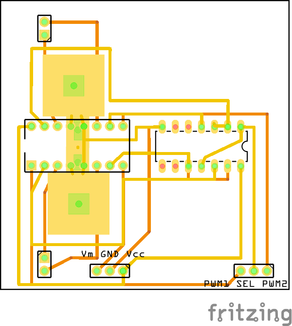
For the H-bridge I decided on the L293D. Yes, I am aware that the max current should be limited to 600mA but I'm certain that a low duty cycle will keep me in spec, and if it does go over, should still be fine. I'm designing the boards to enable efficient active cooling should it be needed.
To save on the amount of pins needed on the MCU, I went with a 7404 inverter chip to disable the reverse windings when forward is enabled, or vice versa. Both motors driven by one L293D will be fed with the same direction control line, as I will never run both pumps simultaneously in this application. The PCB does have an option to easily incorporate a second line if you need though. I'll be using a full hex inverter per dual H-bridge just to minimize extra wiring and make future additions simpler.
At first I wanted to make a larger board with enough H-bridges to control all pumps necessary, but then decided to rather go with smaller modular boards for a few reasons:
- To eliminate the need for via's
- To simplify the PCB design
- To make production more cost effective as it is cheaper to produce multiple small boards than one larger one. Also, many pcb houses sell boards in multiples of 3, so then I'll waste less boards.
- To help aid in cooling
I have no idea if the H-Bridge will heat up much, so I will design it with some passive cooling and in such a way to enable active cooling easily. If it is not needed, then nothing is lost. The boards will include a copper pad on each side of the L239D soldered to the GND pins as suggested in the Application Notes. The modular boards will sit stacked perpendicular to the main board on 90 degree male headers. The pads on each board is placed in such a way that if a small brush-less fan is applied to one side of the stack, nothing will block the air flow over them.
The board will have 6 inputs and 4 outputs. The inputs will be (on 90 degree male header pins) Vcc (supply voltage for the two chips), Vm (motor supply voltage), GND, PWM1/2 (PWM control line for each of the two motors) and SEL (which is the directional selector). The outputs will be screw in terminals for the two motors.
That's it for now. I got so confused laying out the board, that I gained new respect for people doing this for larger projects. I mean, this is a VERY simple board. I'll appreciate any feedback as I normally stop my builds at bread-board level.
Happy Head-scratching
Discussions
Become a Hackaday.io Member
Create an account to leave a comment. Already have an account? Log In.
https://hackaday.io/project/1838-Open-Syringe-Pump
Also, if you decide that you want to minimize moving parts in this project to reduce maintenance, maybe look into inkjet technology. It's mature and really good for dispensing tiny amounts of liquid accurately and reliably.
Are you sure? yes | no
Are you sure? yes | no