 DigiGram
I've been playing with the idea for a detector based on colorimetry for a few years now. Using RGB led's and a LDR It works okay on hard surfaces, but measuring liquid colours has proven troublesome for me.
After some soul searching and thinking back to ways we used spectrometry in the lab, I realised that I should be able to measure obscuration (how much of a beam is "lost" in the medium) as that should increase/decrease depending on the colour and/or colour intensity of the medium. So in theory, if I send a red laser beam through an orange medium I should get reasonable amount of light on the other side. If the medium changes colour to bright red, I should be getting more light on the other side. (side note, I'm reasoning that a red fluid absorbs all other colour light and lets only red pass, if I'm somehow confusing the physics here, the results will be exactly opposite, but still usable.)
So, how to measure this obscuration? I decided to go with a red laser diode (based on the price, nothing else thus far, will conduct experiments later to establish if it was a good choice). On the detector side I can use a photo diode, photo transistor, photo resistor or a LED. It seems like using a red LED will focus more on the red wavelengths that pass through, which (in my mind) is beneficial to me, but again, I'll use different sensors to see what works best for this specific application. I do not really need speed as I'll do the tests slowly to give some mixing time, as well as cooling time for the pump-motor drivers.
So that brings me to a highly premature circuit board for the application. Note that the laser diode is represented by a LED and that the space between the diode and LED is roughly 2cm for the optic cell. The header pins will be used to interface with the main board where V (Vcc), Do (Data out), G (GND) and Di (Data in) will connect to the ATmega. Note that Vcc will be unregulated.
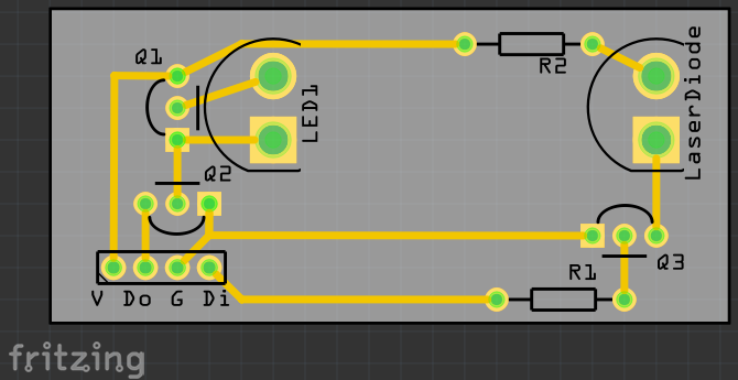
As with any project that is done without physical trials, I know something, somewhere will not work, but that is part of the fun.
Happy Detecting
Discussions
Become a Hackaday.io Member
Create an account to leave a comment. Already have an account? Log In.