After the decision for the microcontroller is done we need to make decisions for the basic board layout. This also includes the choice of housing for the MOSFETs. The basic choice here is whether to use SMD fets or THT fets. As we want to run up to 1000W through the board the choice of THT is more sensible and TO-220 is a good form factor with a large choice of products.
Let's do a quick back-of-the-envelope calculation. We have 50Volt from the battery and we want 1000W output. Thus we have at least 20A going through the fets. However, the controller acts together with the inductance of the motor as a DC/DC converter and the amperage can thus be even higher unless being limited by the firmware.
So we'll assume 50% margin which results in 30A. The on-resistance of a reasonable MOSFET is around 5mOhm. Thus we have 30A*30A*0.005Ohm = 4.5W. As a rule of thumb a TO-220 can dissipate roughly 1 Watt when not mounted on a heat sink. Thus at 1000W we need to properly mount them on the enclosure.
Here is a picture of the general layout in a 3D rendering from KiCAD:
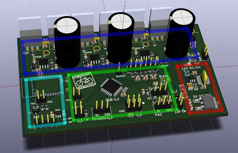
The board measures 100x60mm. The board is properly designed into sections. The dark blue part is the power stage. The power stage contains the 6 MOSFETs, the 3 half bridge drivers with boot strap circuitry and the caps.
The green part is the brain with the uC and various I/O connectors for throttle, hall sensors, brake, speed sensor, pedal sensor and ICSP.
On the right side in red there are the power regulators. The top one converts the 50V from the battery to 12V for driving the fets. It has 0.6A output thus can produce up to 7.2W. The board itself needs about 1W so we have 5W left for LED lights on the bicycle. Below is the old classic 7805 linear regulator for powering the brain.
Finally we have on the lower left the bluetooth section. This contains another voltage regulator for 3.3V and a logic level converter for the 5V TTL to 3.3V TTL.
That's it, stay tuned for the next diary entry!
Discussions
Become a Hackaday.io Member
Create an account to leave a comment. Already have an account? Log In.