Assigning the pins is quite a puzzle. We have digital pins and analog pins, pins that need to do PWM and pins that need to do serial output. Other pins need to be connected to interrupts. Thus we need to juggle assignments until everything fits.
The pin assignment on the controller looks like this:
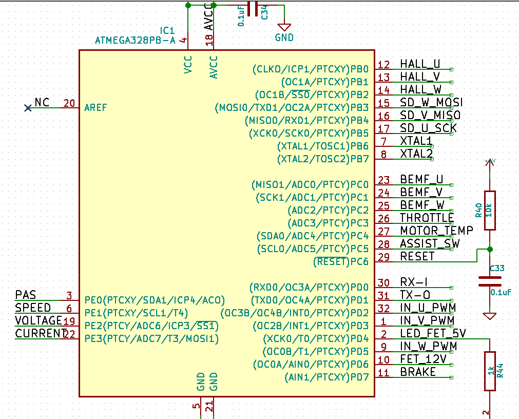
First consideration are the PWM pins for driving the half bridges. This could either be the OCxA or the OCxB pins. The OCxB pins allow for a more flexible configuration thus we'll use PD2, PD3 and PD5. Next we assign the hall sensor pins. These are digital and should be next to each other and more importantly they need to be on the same port to generate the same interrupt. PB0 to PB2 is the good choice. Next we assign the 3 shut down pins for the half bridges. For ease of programming they should be next to each other and on the same port. PB3 to PB5 are free and fit these conditions. Also fixed are the serial pins for the communication with the bluetooth chip. Thus PD0 and PD1 are used as RX and TX lines.
Pins needing analog input are the BEMF pins. These are for voltage sensing on the phases and can be used for sensorless operation. Then obviously the throttle, the voltage and current sensing and motor temperature. Last not least we use an analog pin for a three button switch together with a resistor network.
Further inputs are brake, speed and pedal sensors. They are all digital inputs with no specific requirements.
This leaves us with two pins of which we'll use one for a blinkenlight LED and the other to switch a small MOSFET for the bike light or for a brake light.
Discussions
Become a Hackaday.io Member
Create an account to leave a comment. Already have an account? Log In.