 Timo Birnschein
cnc_gcode_controller is an amazing open source project. As far as I'm aware, it has the only open source auto level feature that properly works by probing the board, creating a height map of it, and then splitting all the gcode commands up into snippets to linear interpolating them in the Z-Axis to match the the actual PCB or bed shape. When it works, it's fantastic!
However, GRBL1.1 changed a few things around and, of course, it didn't work anymore.
First of, GRBL1.1 uses a separate probe pin on the Arduino and the previously used Z-MIN/MAX pins won't do it anymore. The probe pin is now also reported with a 'P' instead of a 'Z' when asked what endstops are hit using '?'.
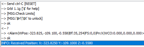
In the above example right after power up, the X axis endstop is reported shown in the |Pn:X| section.
Then, when the probe pin is hit, the command to let cnc_gcode_controller or any other gcode sender know where this was, is also different so cnc_gcode_controller didn't interpret it properly. I went ahead and created some issues around it on github and the original author (Patrick) quickly reacted and fixed the issues I described. THANK YOU!
In addition, I decided to add a few buttons to the software to make my workflow a bit easier.
The Advanced Controls panel now contains a second row of buttons underneath "Global" specifically for "Milling".
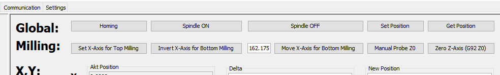
These buttons allow me to easily invert the X-axis and move the tool over to the other side of the bed to a calibrated location to create perfectly aligned double sided boards without the need for any alignment pins. Just flip the board over, align the same corner of the PCB used for the top side and align it with the bottom side on the bed, done.
The Skew-Problem
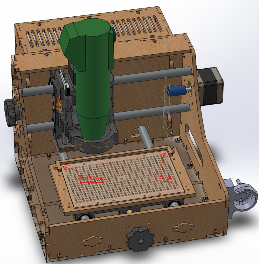
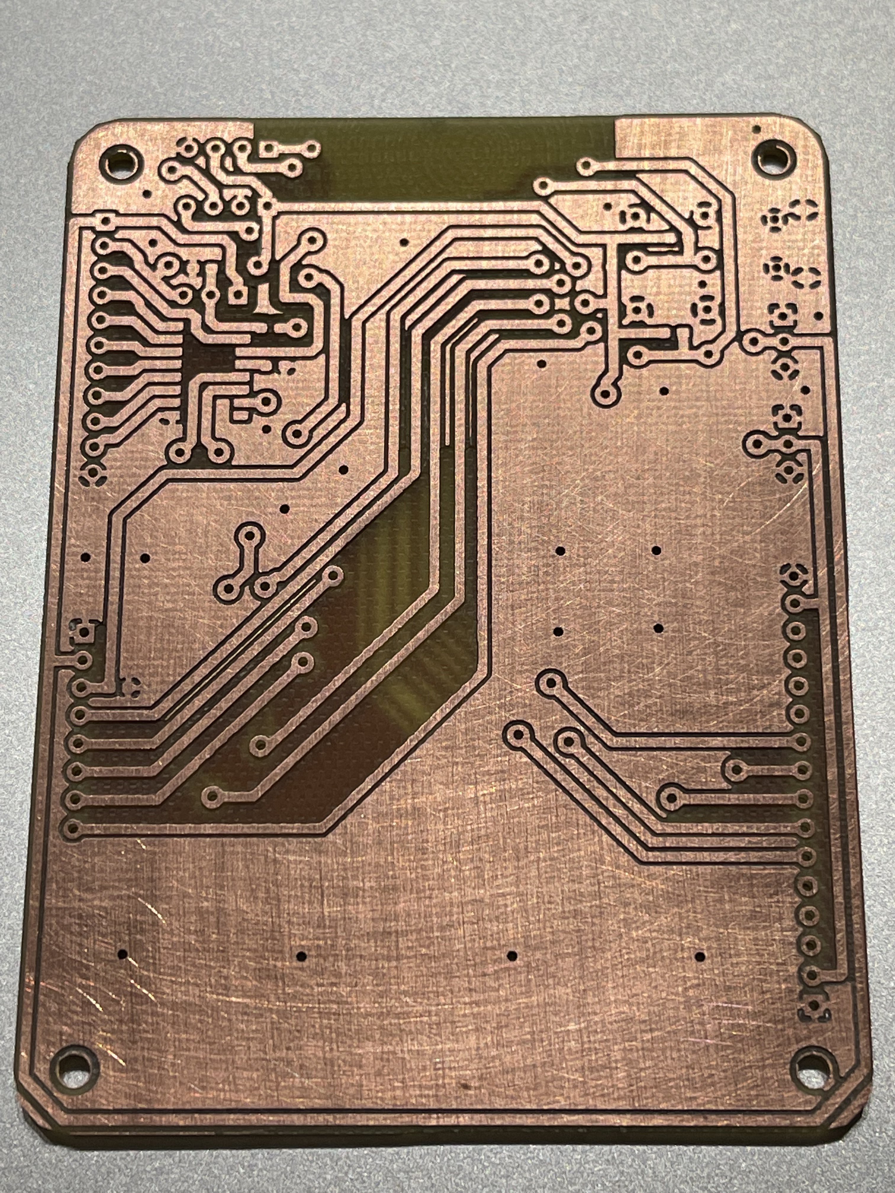
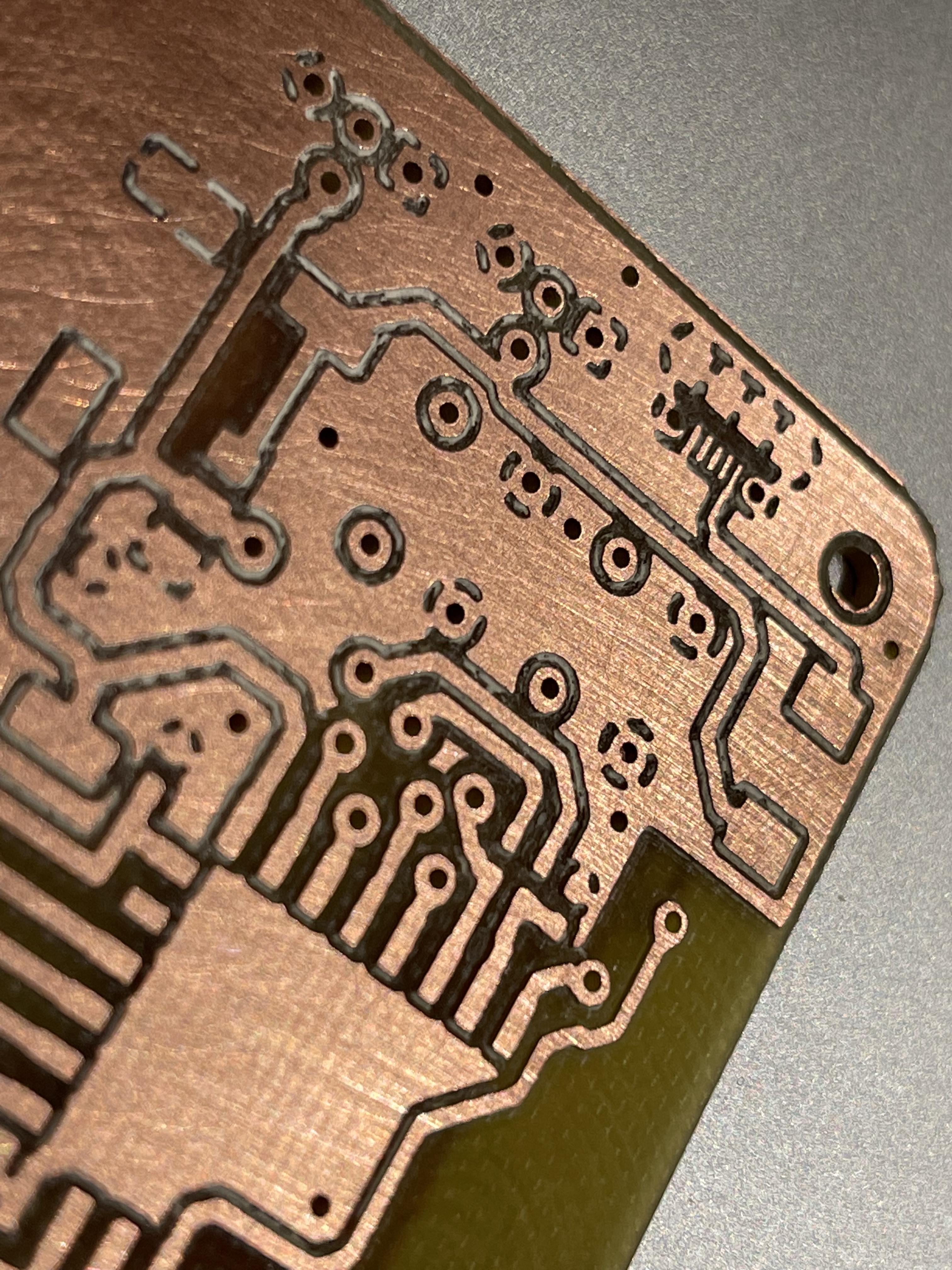
After calibrating the machine offset for top and bottom milling perfectly after many trials of milling and drilling test patterns, my mill appeared to work perfectly. As long as you only want to mill at the very bottom of the bed. Turns out, the machine is skewed. It has a parallel shift along the Y-axis resulting in parallelograms rather than squares. The lower 10mm of the board look great while the upper 75mm go more and more out of alignment with the bottom side of the PCB. All consequently drilled holes on the bottom side are therefore misaligned with the vias on the top side. Extremely annoying and in this case breaking the layout as some connections are broken now.
At first, I was confused about this but it occurred to me that I used my $350 Chinese K40 laser to make the PCB mill which most certainly is not 100% square looking at the way it's put together. It's sturdy but there is a different between something being ridged and something being well aligned and calibrated. So the cnc is skewed because the base plate of the cnc is skewed which in turn is skewed because the laser cutter is skewed. hmmmm...
How can I fix this? Turns out it's very easy to do in software.
My first thought was to write a python script to ingest the gcode and translate every X-Coordinate based on it's corresponding Y-Coordinate. However, that's a lot of work and it felt like a waste of time for the number of boards I make a year.
I found a much more elegant way to do this: In the grbl1.1 preprocessor of FlatCAM, I added an equation that just adds an offset to the X-coordinate based on Y. I just need to flip the sign for the other side of the PCB so I created a second preprocessor script that does just that. Problem solved :)

I then presented this idea to the developer of FlatCAM which is my favorite PCB CAM software of all time. He liked the idea as it turned out his personal machine also has a skew, so he went ahead and implemented a variant of it into his software!
In my version, I created two different preprocessors for GRBL1.1. One for top side milling and one for bottom side milling. This works well for me as I only need to change one thing in FlatCAM during the creation of the CNC commands to correct for top and bottom skew. The issue my setup poses is that flipping the board over means the skew technically inverts as well. So I either have to have a checkbox or a flag of some sort to select top or bottom or I’d have to change the skew in the configuration settings every time. Selecting a different preprocessor seemed easier to me, for now.
Just to show what this code does, here is an exaggeration:
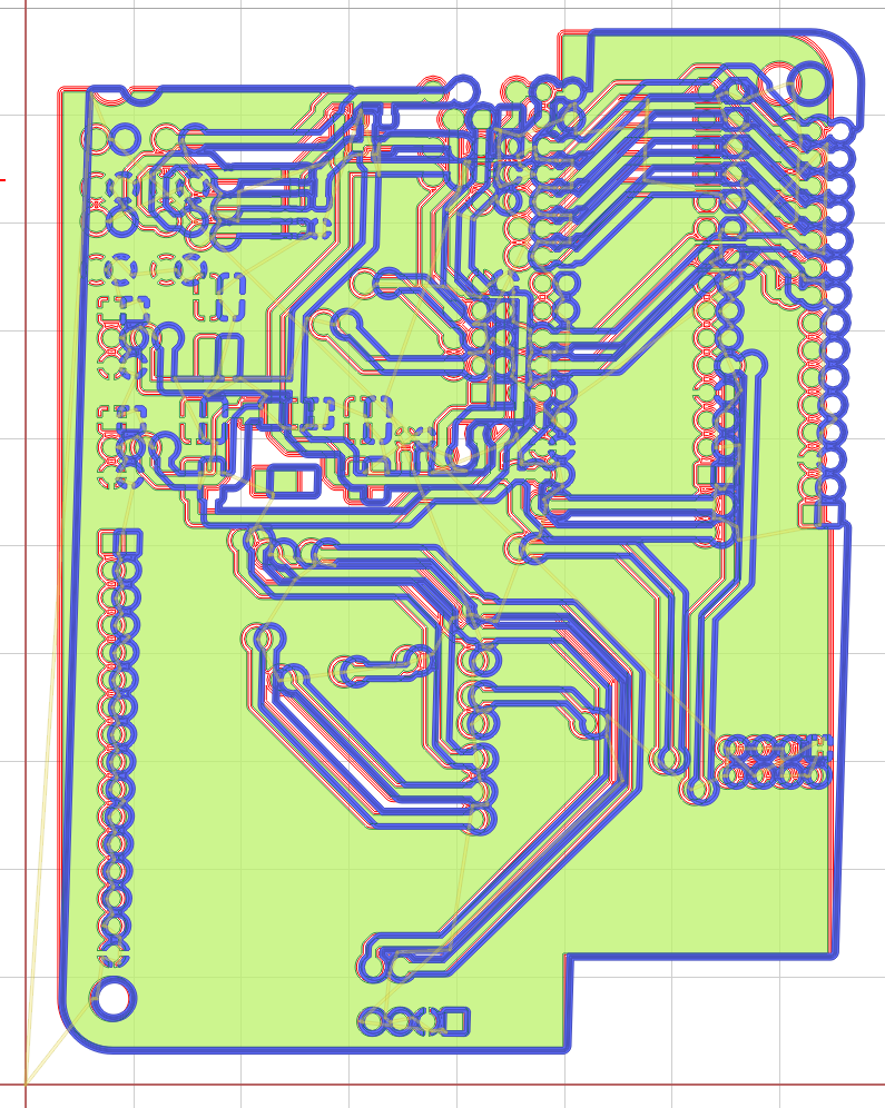
Another large amount of calibration mills and drills later, I ended up with near perfection from a $200 mill that was made on a $350 laser (plus some upgrades). That is pretty nice in my book and at the moment at least I could not be happier with the results!
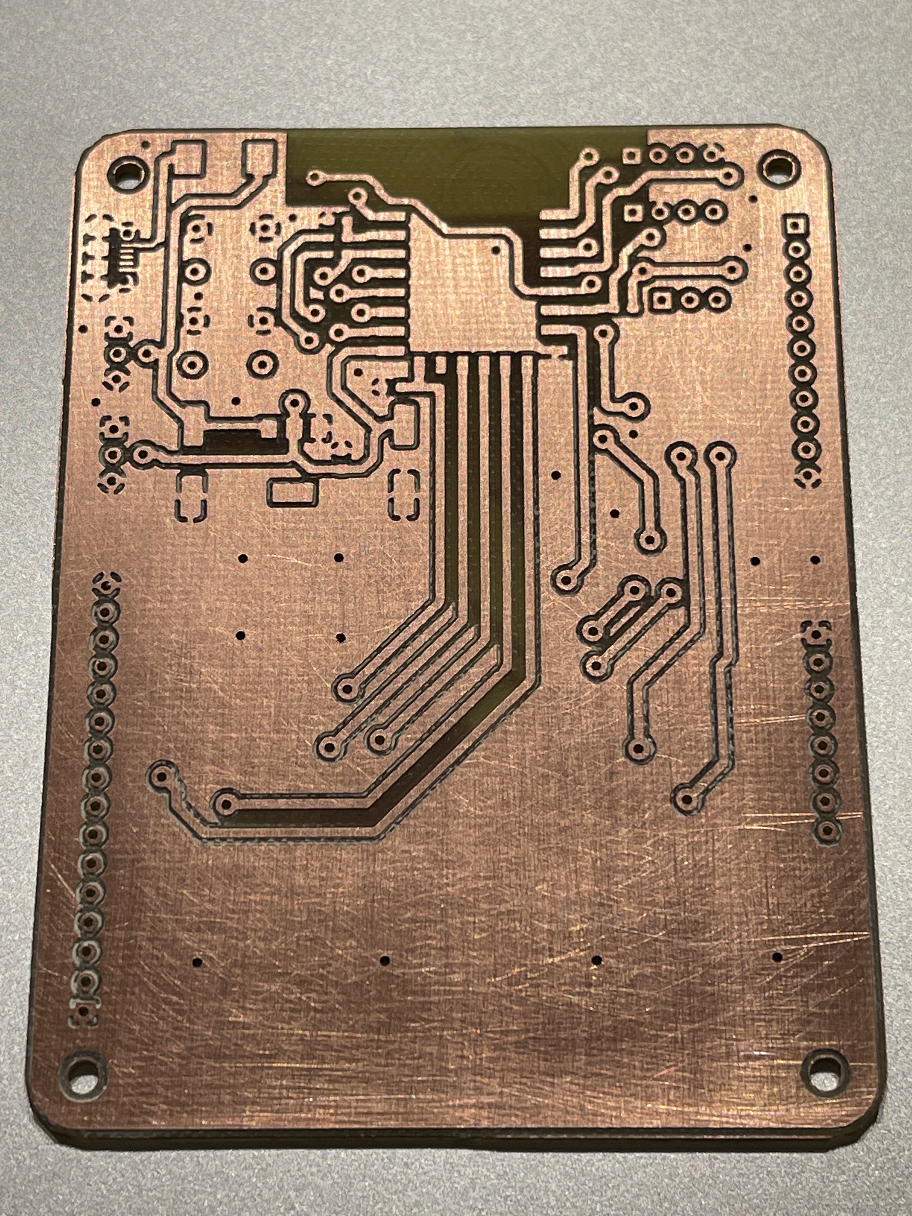
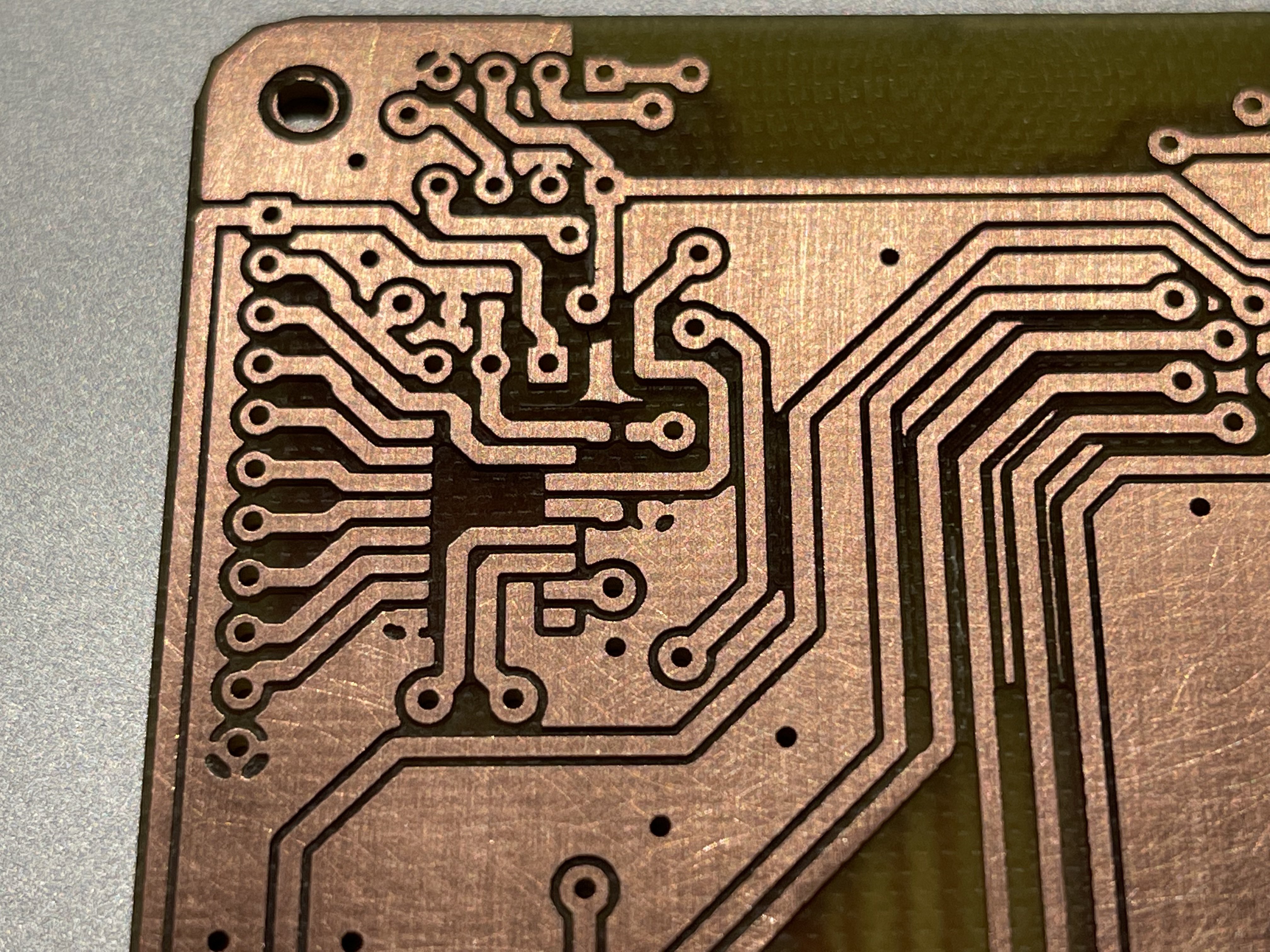
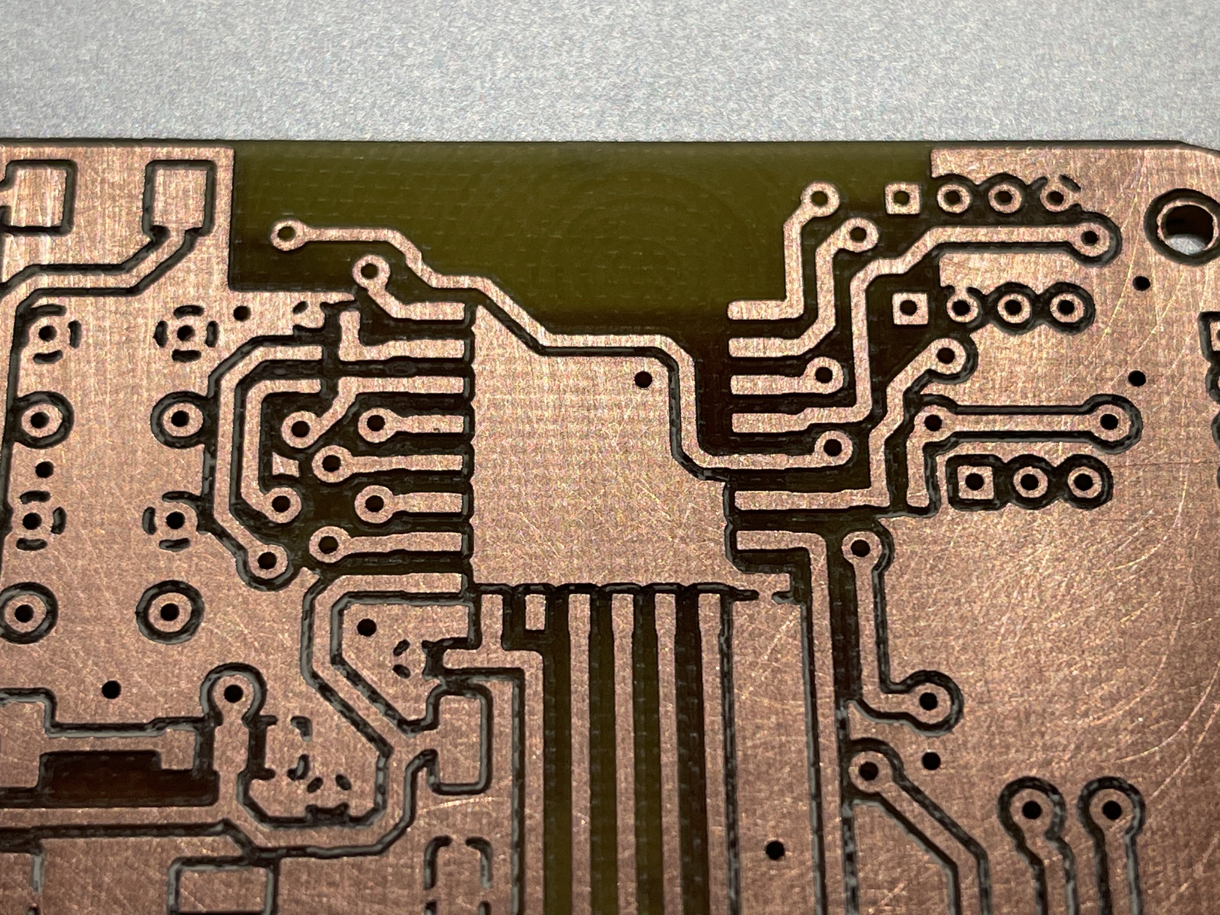
As can be seen, top and bottom alignment is near perfect and does not need to improve at this point. I’m going to experiment with thinner traces and smaller vias now as the reliability has gone up so much with all these changes and I can dare to try this again :-)
Discussions
Become a Hackaday.io Member
Create an account to leave a comment. Already have an account? Log In.
+1 for FlatCAM.
I'll have to check out cnc_gcode_controller - I guess I missed that when looking at options earlier.
For info: bCNC does autoleveling.
Are you sure? yes | no