 Matthias
The schematic is already done. It is attached to this project as a PDF file. You can also find it here:
I release this schematic as CC BY-SA 4.0.
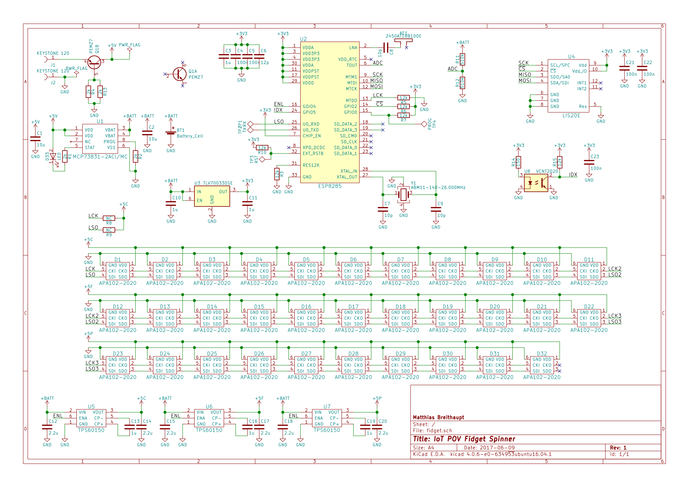
In the top left corner, you find the LiPo circuitry. The cell can be charged by a MCP73831. This is an IC, I used previously. It works very well in cases like this.
The 3-4.2V from the LiPo go through a TLV70033 LDO to power everything except for the LEDs. The LEDs are in two strings of 11 and (due to space restrictions) one of 10. These are each powered by a TPS60150 (at the bottom). Since this chip can only provide 140mA, the LEDs should be driven with only half the maximum brightness or less. Since there are a lot of LEDs in a small area, that should still be plenty. I don't want to blind the user!
In the top center, you find the ESP8285. The LEDs are connected to the I2S pins, the battery voltage can be measured using a voltage divider (R11 and R12). The HSPI port is connected to the accelerometer, which you find on the top right. Last but not least, there is a VCNT2020 optical sensor. I intend to use this to get an index signal.
This index signal will allow both the proper operation of the POV display, but also gives me the ability to measure the time per revolution. Due to this, the users will be able to compare how fast they can spin their device.
Discussions
Become a Hackaday.io Member
Create an account to leave a comment. Already have an account? Log In.
One thing I should note: there I am planning to add a way for the ESP8285 to disconnect itself from the battery (that's what want to use the NPN transistor in the PEMZ7 for). However, I assume, that I won't be able to add it this weekend. That's why the transistor is already there, but not used.
Are you sure? yes | no