 Matthias
As mentioned in my last log, I wanted a way to wake the spinner up by moving it. Also, I want to be able to have the ESP8266 "completely" turn off power until the spinner is woken again. Last but not least, I wanted some kind of relatively fail safe under voltage lockout.
My solution to these problems comes in the form of a little chip made by Silego, the SLG46140. It is a very useful little programmable chip - more or less a mixed signal PLD. I could have chosen a smaller version, but the SLG46140 is the smallest one that is also supported by open source tools, so I thought that would be nice. Even though I am currently using the Silego tools, that is the only proprietary software I use(d) while designing this project.
So back to the fun stuff:
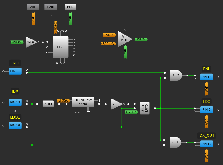
What you see here is my design for this chip. As it handles all the stuff described above, here is a little breakdown:
Most importantly, I use an analog comparator (CMP0) to make sure the battery voltage is above 3.0V. The hysteresis is configure to make sure that the voltage reaches at least 3.2V before setting UVLOn again after it dropped below 3.0V.
Next, I use P DLY to detect falling edges coming from the hall sensor. This signal is - together with a roughly 109Hz clock - fed into CNT2. CNT2 is a counter that counts up to a value of 43, which takes about 400ms at 109Hz. When it reaches this value, it does not automatically reset, but stays there and turns the output on until it is reset. By inverting this signal, I get a signal that is high for 400ms and then turns low if the hall effect sensor does not encounter a new magnet within those 400ms.
The LDO is controlled by the pin labeled "LDO". It is configured as a push-pull output. To control this signal, I used LUT0. This LUT is configured as UVLOn && (!CNT2 || LDO1). Therefore, if the battery voltage is above 3.0V, the LDO is on for 400ms after every turn or longer, if the CPU wants it that way.
So here, we already have the whole wake up by spinning, go to sleep from CPU stuff solved.
The remaining circuitry is relatively uninteresting. It only makes sure that the LED regulators can only be turned on if the LDO is on and also, that the CPU can not mess up the index signal when it is turned off. Since the CPU is running at 3.3V, while the PLD could have up to 4.2V running through it, IDX_OUT is configured as open collector and the CPU has to enable an internal pull up to 3.3V.
Discussions
Become a Hackaday.io Member
Create an account to leave a comment. Already have an account? Log In.