Roberto Innocenti
-
fine tuning firmware for u-boot and develop Radeon driver for latest u-boot version
11/18/2023 at 18:12 • 0 commentsit’s a quite some time has passed since the beginning of July when we posted about the start-up ramp that carefully calibrated, programming a complex integrated circuit with some logic (i.e. ramps, voltage thresholds, internal ways of making the PWM regulator work, and so on) and when the Complex Programmable Logic Device (CPLD) (Lattice LCMXO640C-3TN100C FPGA) was programmed for the very first time in order to manage all external peripherals connected to it.
In July we figured out that a Jtag Debugger was very needed to debug our Powerboard Tyche, the only way to solve the causes of not seeing any U-Boot output. We were able to buy such a debugger thanks to the donations we are collecting with the current campaign, we thank all donors for their support.
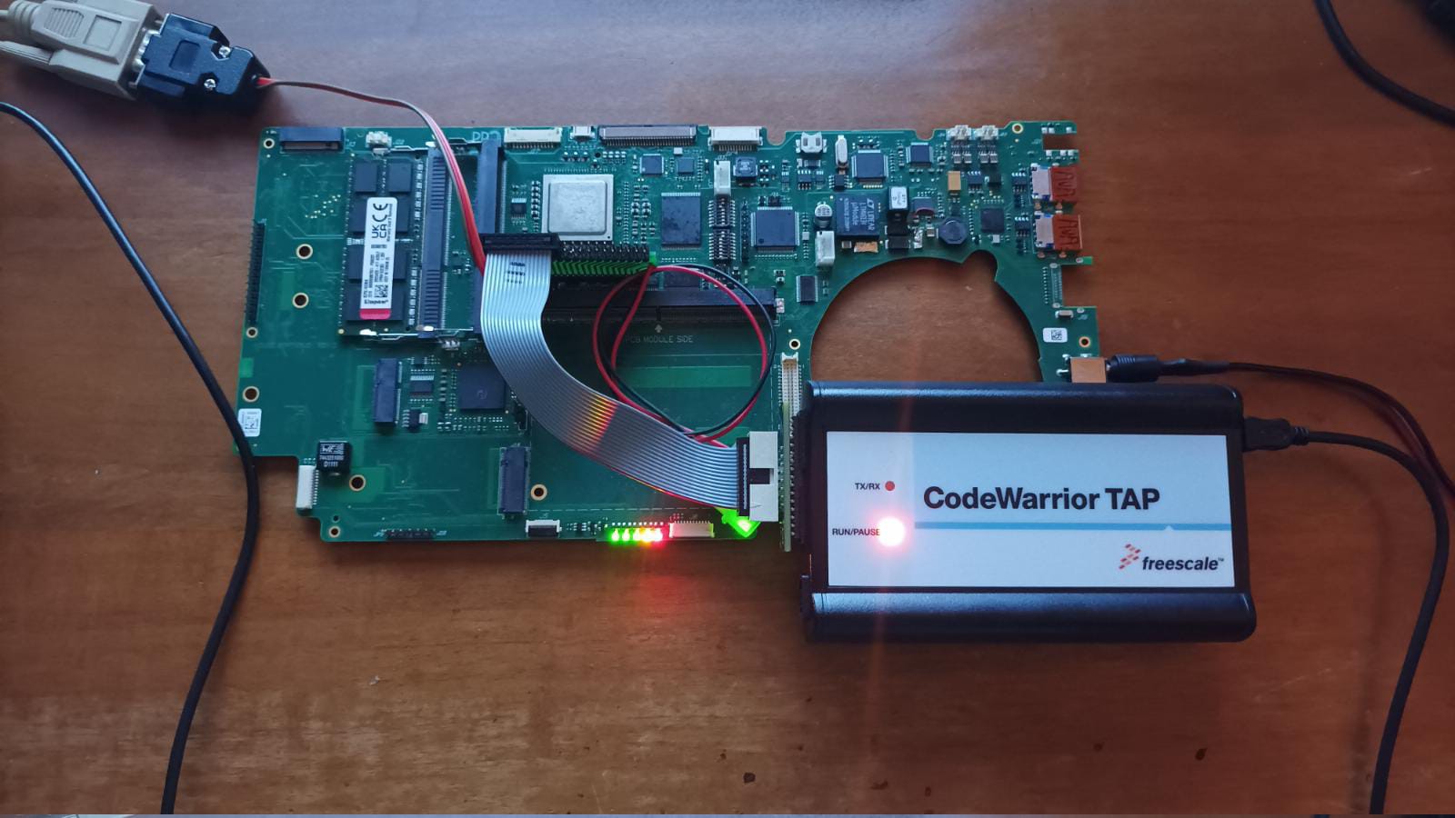
The debugger is the NXP CWH-CTP-BASE-HE Jtag Debugger + NXP CWH-CTP-COP-YE “Probe Tip, Removable, For Power Architecture Processors, JTAG to CodeWarrior TAP Base Unit” and, together with one of the three prototypes, we shipped it in August to Max Tretene that kindly accepted to be directly involved in the debug process of the motherboard. Soon, the task proved to be quite challenging, so after an internal discussion, we decided to offer Max a reimbursement for all the time he was spending on the job, a reimbursement that was made possible to the donations we are receiving with the current campaign.
![]()
Dealing with hardware debugging is quite a hard and tedious job, and it was not easy to see something useful on the Jtag Debugger connected to the prototype motherboard. An additional adapter was required to attach the debugger because of the difference in the pin dimensions (2 vs 2.5). Max found it quite useful using the jtag debugger with our NXP T2080-RDB Devkit that was also shipped to him, because it allowed to test the procedure on a working platform and helped understanding the right configurations of the switches to boot up the board.
![]()
![]()
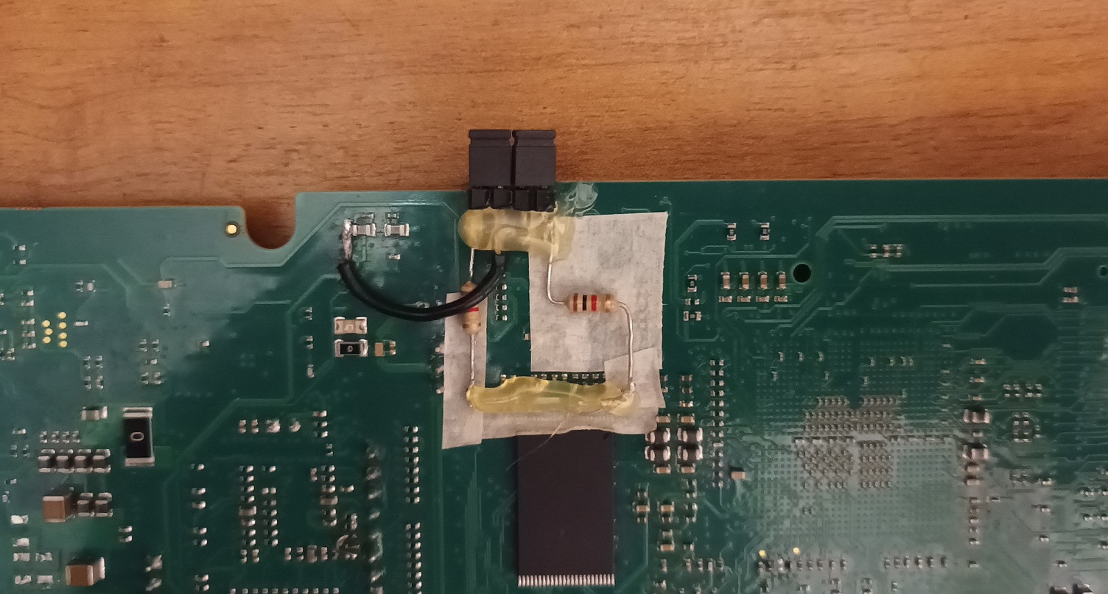
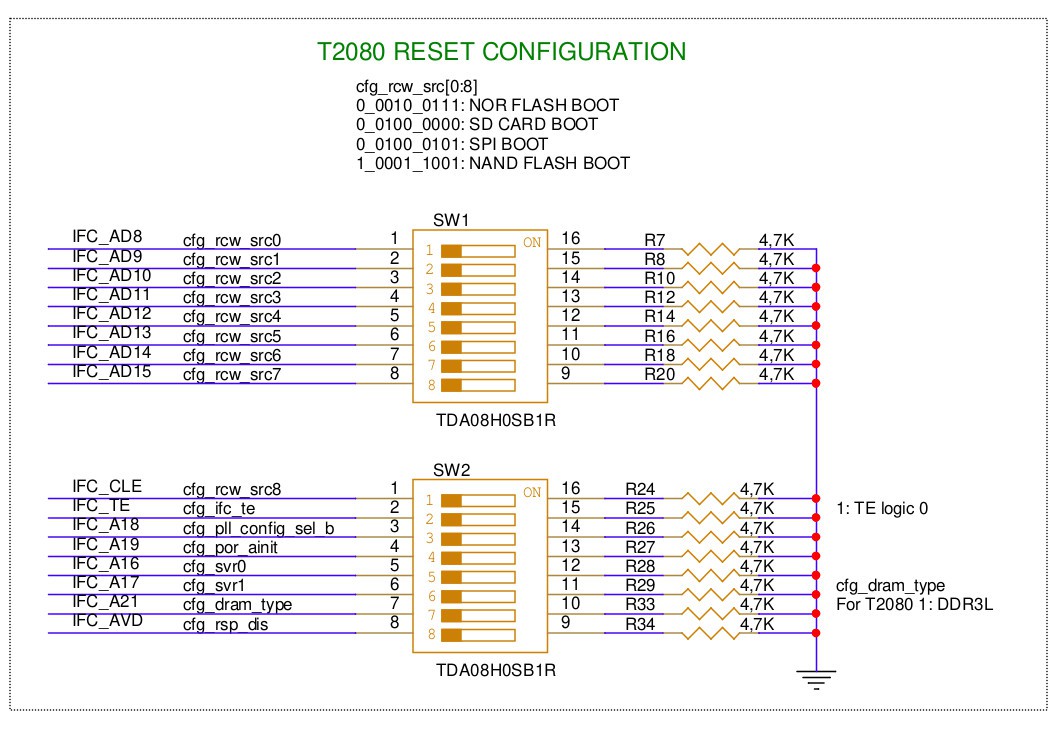
As our PowerBoard Tyche have not the third switch like the NXP T2080-RDB Devkit a few additional resistors were required to setup correctly the board to be able to switch on the Code Warrior debug connected to our Powerboard Tyche. Not just that, an additional update to the CPLD chip was required to setup the debugging system correctly. Finally, on the 16 of October, Max was able to see some sign of life from the NXP T2080 CPU on SRAM and on NAND Memory, as you can see in the screenshots below. These days we are working on NOR programming, waiting in the meantime for a CPLD update from the hardware designer. The NOR programming is needed to have access to the DDR and then start U-Boot.

SRAM programming – CodeWarrior® Development Suites for Networked Applications attached to Powerboard Tyche 
NAND Programming – CodeWarrior® Development Suites for Networked Applications attached to Powerboard Tyche Some possible changes to the hardware design
All these hardware tests were useful for planning some changes to the hardware design: few missing resistors for enabling the u-boot switches must be added and we need to move one chip because it does not fit quite right in the eclipse chassis.
The recent worldwide electronic components shortages we faced when making the prototype Powerboard Tyche boards caused an unexpected -and incredible- increase of the prices. More recently chip prices seem to be coming back to more reasonable prices, with the exception of the Marvell Sata3 controller.
As a consequence, we are evaluating the removal of the Marvell Sata3 controller to both free very-much needed space space and save some costs because at the moment such a chip costs around 90 euros per piece, quite a lot.
In fact, nowadays most SSD are available at a very good price with the M.2 form factor, so a Sata3 connection is not that essential anymore. People in a desperate need for a Sata connection could use the two Sata2 controllers inside the T2080 CPU.
Below we list the availability and prices of
- Marvell Sata 3 controller 88SE9235A1-NAA2C000, in 2022 we had payed around 130 euro per piece + VAT, 1 per PCB, total 3 pieces. NOW Win Source In Stock, 3450 pieces 87 euro
- TPS544B20RVFT 4.5-V to 18-V, 20-A synchronous SWIFT buck converter with PMBus programmability and monitoring in 2022 we had payed around 550 euro per piece + VAT, 1 per PCB, total 3 pieces NOW: TI Website: 2000 pieces around $8 per piece
- 6-port, 12-lane, PCIe 2.0 Packet Switch PI7C9X2G612GP – Diodes in 2022 we had payed it around 250 euro per piece + VAT, 1 per PCB, total 3 pieces NOW Digikey 121 pieces 25 euro per piece
- Surge Suppressors 100V OV, UV, OC and Reverse Supply Protection Controller with -50mV Reverse Threshold LTC4368IDD-1#PBF in 2022 we had payed it around 100 euro per piece + VAT, 1 per PCB, total 3 pieces NOW Mouser 2.191 Unit Price around 4-5 Euro
Compile and test of an updated version of U-Boot
We hired Bas Vermeulen to obtain a running version of the most recent version of U-Boot on both the NXP T2080-RDB Devkit and on the Powerboard Tyche prototype. In addition, we asked him to develop an AMD/ATI Radeon driver for U-Boot, a work that he carried out last August. The results of his effort is publicly available on our GitLab U-Boot repository.
Unfortunately, until our Powerboard Tyche will not be able to reach the U-Boot startup process, Bas will be limited in developing and testing U-Boot on the NXP T2080-RDB Devkit. For that reason, Max Tretene is actively supporting Bas in testing the U-Boot binaries generated by Bas on the Devkit.
As you can see on our U-Boot gitlab repository, Bas was hard at work compiling very recent versions of U-Boot during last August. Unfortunately, because of causes of force majeure, Bas was unable to continue working during September, but he should be back on track the very next days.
Below a short list of the main issues Bas is working on:
- The ati_radeon_fb driver is no longer present
- Configure the device tree to support the correct PCI spaces
- Create a driver for the AMD/Radeon GPU
We finally thanks again for your support and donations that allow us to finance all these activities, greatly facilitating reaching our goal in a reasonable amount of time: a very good quality PowerPC based notebook release as open hardware.
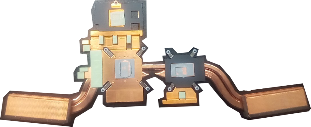
We still do not have yet a formal quotation of the design of the heat pipes for cooling down both the CPU and the MXM video card. Informally, we estimated approximately 10000 euros. At the moment we are very much focused in making the Powerboard Tyche prototypes working, at least up to the point of being able to launch U-Boot.
more info...
-
Working on u-boot even with jtag debbuger and redesign of heat pipes
07/02/2023 at 12:36 • 0 commentsOnce again we want to thank you all for the great support and great enthusiasm you demonstrated during the CE mark donation campaign. We ended the campaign with a total amount of 12500€ (https://en.wikipedia.org/wiki/CE_marking), this is a huge milestone for us all and we are so very grateful.
By financing the CE mark certification you have shown us that you believe in the project and our vision of creating a fully open hardware notebook motherboard based on the alternative PowerPC CPU architecture.
We closed the campaign with around € 4000 more than expected, and this extra money will cover some of the extra and unplanned costs we faced for the increased price of electronic components and the extra costs of the three MXM video cards (360 USD each).
The CE mark certification is a mandatory requirement for selling electronic products in the European Union. It ensures that our notebook motherboard meets the safety, health and environmental standards of the EU. Without it, ACube Systems would not be able to launch and sell our Notebook on the EU market. Getting the CE mark certification is not an easy nor a cheap process as it involves rigorous testing, documentation and quality controls.
![]()
However, the CE certification process can be performed only when the product can be considered completely finished, and that means once the board works, the cooling metal pipes are in place and all is assembled into the selected slimbook eclipse chassis.
Current activities
The Tyche Motherboard has surpassed all the electrical checks, and now the the key activities being performed concentrate on the hardware initialization procedures.
The start-up ramp was carefully calibrated, programming a complex integrated circuit with some logic (i.e. ramps, voltage thresholds, internal ways of making the PWM regulator work, and so on).
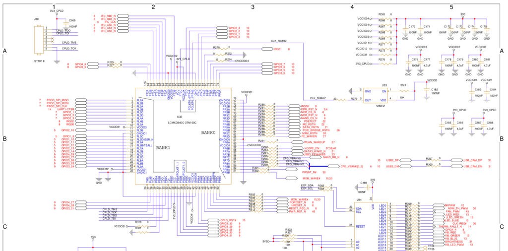
The Complex Programmable Logic Device (CPLD) is a Lattice LCMXO640C-3TN100C FPGA is programmed to manage all external peripherals connected to it (see the block diagram and wiring diagram on page 15), manage the interrupts, data, boot reads, set resources according to the CPU and is able to reset all peripherals.
![]()
Working on U-Boot
Currently, a small team of volunteers are working on U-Boot . We are decided to buy a JTAG debugger, a quite useful tool indeed that will make the hardware debugging much easier.
We learnt how to configure and build U-Boot, and we set up a cross-development PowerPC toolchain and the related Device Tree Blob that is used to describe the physical configuration of each hardware component available on the motherboard. You may keep an eye on our attempts by looking at our GitLab pages. We started by re-compiling our old U-Boot binary dating back to 2019, the one that we are currently using on our NXP T2080RDB devkit and also trying to compile a newer U-Boot version from a the DENX mainline vanilla branch without our patches. We are now kindly assisted by Max Tretene, the same guy working at ACube Systems that compiles U-Boot for their motherboards such as the Sam440 or the Sam460ex. Max is currently available to introduce hardware support to AMD/ATI Radeon graphics cards in U-Boot, (ndr.: he recently told us that his spare times is not enough so we are proposing him to work under payment) stay tuned for more in-depth posts about it. In the hope of speeding up the development, we provided Max Tretene with our NXP T2080RDB devkit in early June.
We want to thank the dedicated small group of volunteers and especially Max Tretene for their precious spare time spent in trying to configure and compile U-Boot, we very much appreciate their availability and effort, even if a successful result is yet to comes. In addition, we greatly appreciated the offer made by a professional engineer – not to be disclosed yet- that is ready to work for us on U-Boot for a very reasonable amount of money.
Launch of a new fundraising campaign
After quite some internal discussion, we finally decided to launch a new fundraising campaign aimed at support and speeding up multiple actions:
- Buy a JTAG Debugger
- Design of the heat pipes for cooling down both the CPU and the video card;
- Prototype of a heat pipe fitting our Slimbook chassis, a requirement to proceed to the CE certification process;
- Development of an AMD/ATI Radeon driver for U-Boot;
- Development of the device thee to fully exploit each hardware component of the board;
- Compile a custom U-Boot binary from up-to-date DENX sources;
- Provide the entire toolchain for cross compiling U-Boot and the device tree for PowerPC;
- Provide the documentation detailing all the technical aspects of both U-Boot and the device tree so that anybody will be able to understand how to rebuild it from scratch and how to customize it.
In carrying out these actions, we will try our best to optimize both the support of the involved volunteers (any additional help is more than welcome!) and the contracted software engineer(s).
At the moment we only have a rough idea of the amount of required hours of paid work required to complete U-Boot and its closely related device tree. After some internal investigation, a reasonable rough estimate could be at least 100 hours, but it may take more to reach the goal.
We do not have yet a formal quotation of the design of the heat pipes for cooling down both the CPU and the MXM video card. During an informal discussion with electronic engineers that have experience in the design and production of these heat pipes, we estimated approximately 10000 euros.
To sum up, the title of next campaign is “Development of software components and heat pipes for the Tyche Motherboard” and its breakdown costs are the following:
- Around 100 hours of work of a software engineer(s) for the customized U-Boot, the device tree and the AMD/ATI Radeon video driver: 5000 euros
- JTAG debugger 1000 euro
- design of the heat pipes and production of 3 of them for the three prototypes: 10000 euro
The estimated amount to collect with the next campaign is 16000 euros.
We really hope that you will assist us once again during this final journey. We are that close to making it happen: a 64 bit, multi core, PowerPC based notebook fully open hardware with up to today’s standards devices and interfaces!
Donation Campaign Development of software components and heat pipes for the Tyche Motherboard
-
Prototypes testing results
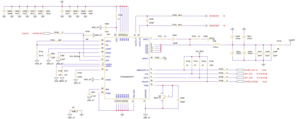
02/28/2023 at 09:52 • 0 commentsThe laptop prototypes testing is progressing great. We tested the primary power supply stage of the CPU, one the most power hungry components in the board, and it is being fine-tuned thanks to a programming apparatus. The chip in charge to power up the CPU NXP T2080 is the Texas Instruments TPS544B20RVFT (Switching Voltage Regulators 4.5-18V 20A SWIFT) as explained at page 37 in our electrical schematics.
![]()
The start-up ramp needs to be carefully calibrated, a complex integrated circuit with a some logic that needs to be programmed to make it work properly (i.e. ramps, voltage thresholds, internal ways of making the PWM regulator work, and so on).
The other power supplies are a half a dozen voltage regulators and are meant to power elements such as the PCIe, the RAM, the internal peripheral buses, the connected devices, the Non-Volatile Memory Express (NVMe) and the clock generators the are essential to make the board work properly. The Eclipse Legacy Battery was tested and is recharging properly.
The Complex Programmable Logic Device (CPLD) is a Lattice LCMXO640C-3TN100C FPGA and has to be programmed to manage all those external peripherals connected to it (see the block diagram and wiring diagram on page 15 ), manage interrupts, data, boot reads, set resources according to the CPU and reset all peripherals.
![]()
So far so good, the electronic design seems to work correctly, at the moment we are only fine-tuning each electronic component. If all checks continues like this, we might end all electronic debugging in the next few weeks and we can consider this very delicate phase successfully completed. After that, we plan to place the first code in the CPLD, and right after that we should be ready to load U-Boot, the first-stage and second-stage bootloader. We are trying to re-patch a recent version of U-Boot, quite some time has passed since we patched it to make it recognizing the graphic board we mounted on the PCIe port on the NXP T2080RDB board. Not just that, we must carefully customize the device tree to correctly map all peripherals available on the motherboard.
If for it concern the electronical components we can safely rely on the (paid) support of an expert engineer, for setting up U-Boot it’s up to us to make it work properly, and more importantly, to make it correctly recognize all peripherals, especially the SD card, the FLASH and, even more importantly, the two DDR3L RAM slots.
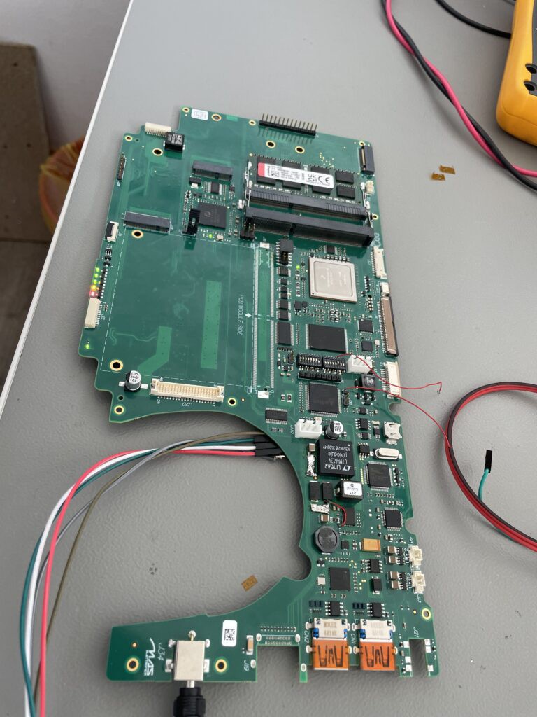
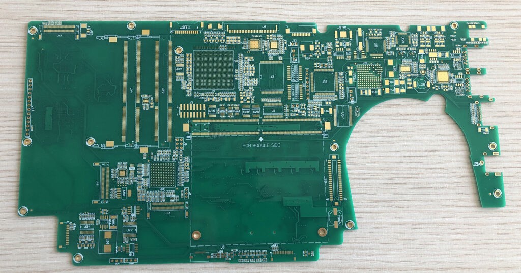
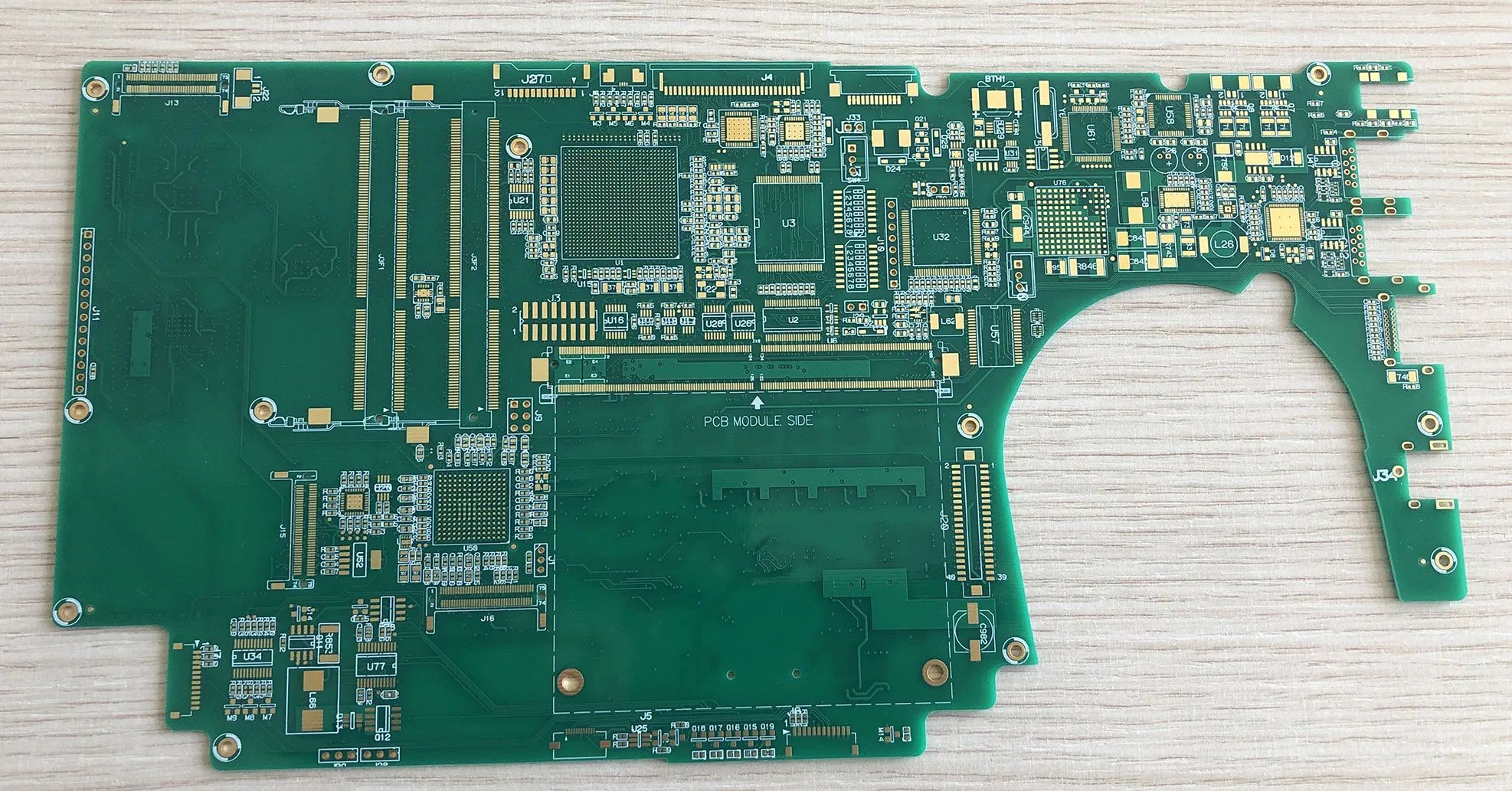
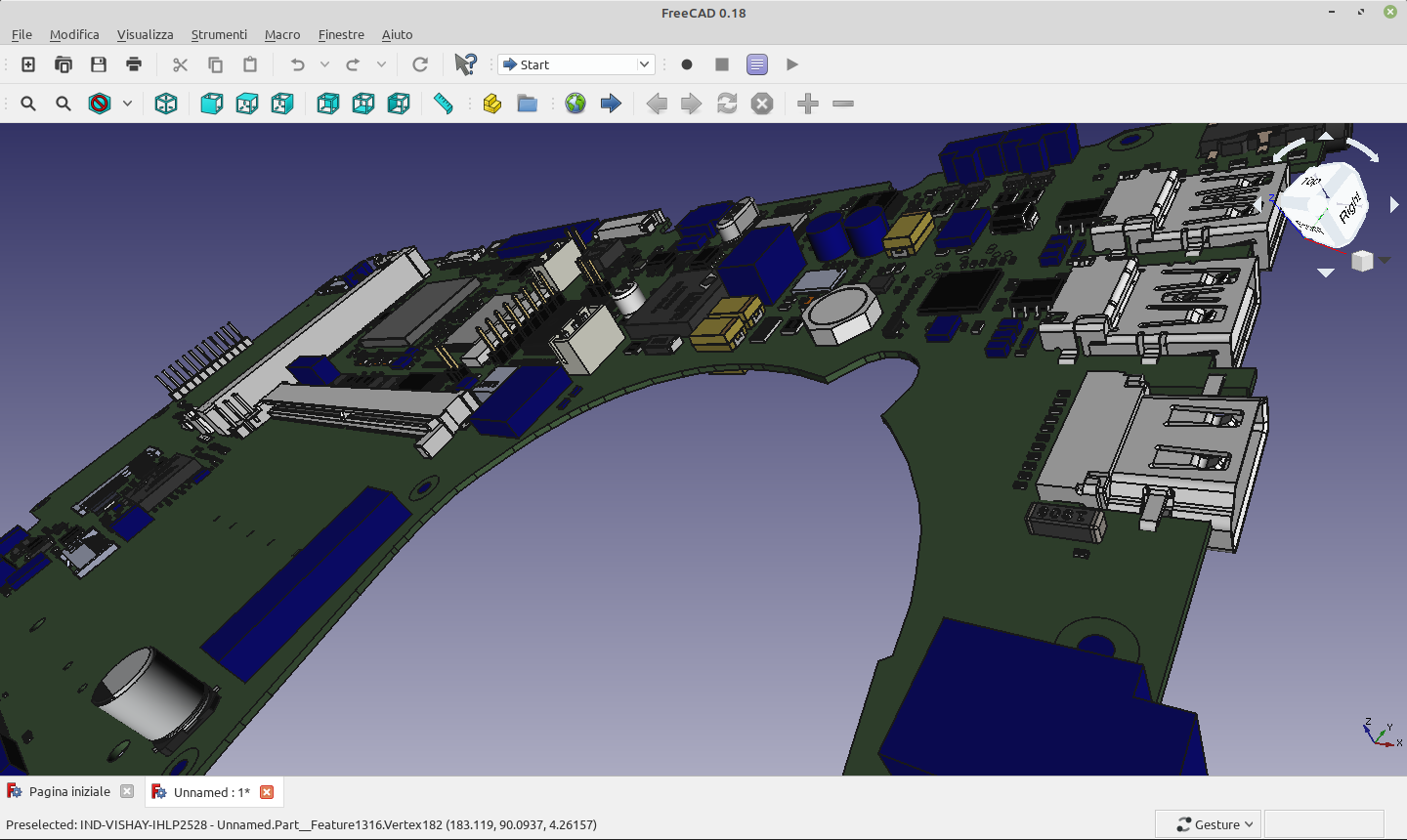
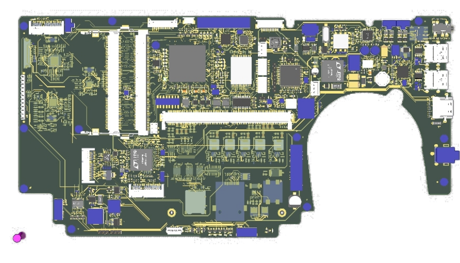
![]()
Powerboard Tyche, top side. The visible biggest gray chip is the CPU NXP T2080 Power Architecture CPU.
We would like to thank everyone for the continuous flow of donations, and please, continue to do so. At the moment we still need funding to cover the extra costs we faced for the simply crazy prices we paid for the electronical components mounted on the prototypes motherboards and especially for getting our hands on two MXM graphic boards based on AMD chips. For two MXM AMD E9174 video cards with 4GB RAM we have spent 780 dollars ( 360 each) and 185 euro of import Tax around 965 euro .Considering all chips, the cost of each prototype resulted 1200 euros higher than what was initially planned 4392 euros more (1200 x 3 + 22% VAT). So we need to collect around 5357 euro more than the goal of the last donation campaign.Donations and professional for u-boot
In addition, after an initial round of experiments, we are still struggling to successfully customize U-Boot and to properly setup the device tree. Most of us already spent quite some time on the task during our spare time (remember, we are all volunteers with a proper day job and a personal life ;), so we are seriously evaluating to assign the job to a professional to get the job done in a reasonable amount of time, and to do that we need your financial support!
More Info -
Ready for Prototypes production with reworked PCB design with all available components
08/29/2022 at 22:41 • 0 commentsPublished Powerboard Tyche PCB reworked source
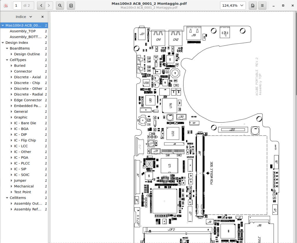
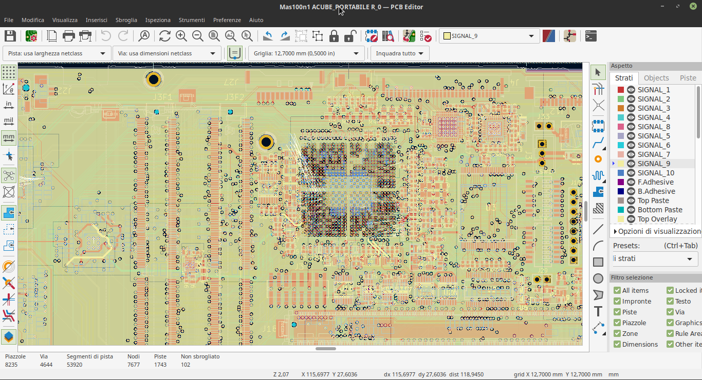
Finally, the reworked PCB design source of Powerboard Tyche with the updated available components is ready ( in older posts you can go more deep about “our” electronic components shortage issues). This work was made using Mentor Expedition and it is ready and uploaded into our repository with all reported issues fixed, including issue number 5, the last one corrected . Thanks to our collaborators we are able to export this work using Altium form so the next days we will publish it and we will try to convert it to Open Source Kicad format ( and probably loosing something in the conversion process) . In our older post we have give more details regarding the PCB sources.
Inside Output folder you can find many interesting files easy simple viewable like the “the plot separate sheet” CAM350/DFMSTREAM and the Motherboard Assembly TOP and BUTTOM.
![]()
As a conclusion now we have everything to produce and make the hardware tests in September.
In July we have published more details about the rework design due to the global shortage of electronic componentsRework of a part of the mobo and situation of the components
As you know, we were having troubles to find a few components in the marked (listed below) not only because of their availability but also due to the increased price. After an extensive research, the designer was able to identify the replacement components.Below, a detailed list of unavailable or extremly expensive parts that the designer is replacing with other readily-available components:
- 1 per pcb Transistor: NPN; BSR17A bipolar; 40V; 0.2A; 0.35W; SOT23 – ON SEMICONDUCTOR > 3100>#/strong### cost increase from 0,5 euro to 16,50 euro per piece
- 4 per pcb Field Effect Transistor –NDC7002N MOSFET 2N-CH 50V 0.51A SSOT6 – ON SEMICONDUCTOR : >1100>#/strong### cost increase from 0,50 euro to 6,5 euro per piece
- 2 per pcb MOSFET N-CH 100V 60A PPAK SO-8 SiR870DP – Vishay Siliconix > 3250>#/strong### cost increase from 1,53 euro to 50 Euro per piece
- 1 per pcb Parallel NOR Flash Automotive Memory MT28EW01GABA1HJS-0AAT – MICRON > 3250% cost increase from 13 euro to 423 euro!!!
- 1 per pcb IC EEPROM 256KBIT I2C 1MHZ 8SOIC AT24C256C-SSHL-B – Microchip Technology > 1000>#/strong### cost increase from 0,29 euro to 2,5 euro
- 1 per pcb 24-bit translating 1.65- to 5.5-V I2C/SMBus I/O expander TCA6424ARGJR – Texas Instruments Not Available
- 1 per pcb 24 MHz XO (Standard) LVCMOS Oscillator ASFLMB-24.000MHZ-LC-T – Abracon LLC – Not Available
- 1 per pcb I/O Controller Interface IC HI-PERFORM LW PWR SM FOOT USB 2.0 HUB USB2514-AEZC – Not Available
- 1 per pcb Two-Lane PCIe 2.0 to Four-Port 6 Gbps SATA I/O Controller 88SE9235 – MARVELL – 980 euro!!!!!!!
- 1 per pcb 6-port, 12-lane, PCIe 2.0 Packet Switch PI7C9X2G612GP – Diodes – 700 euro!!!!
- 1 per pcb Power Switch ICs FDC6331L – onsemi / Fairchild – >3300>#/strong### cost increase from 1,25 to 41,6 euro
- 1 per pcb Switching Voltage Regulators 4.5-18V 20A SWIFT TPS544B20RVFT – Texas Instruments – 90 Euro!!!
- 6 per pcb Switching Voltage Regulators 4.5-V to 28-V, 6-A TPS56637RPAR – Texas Instruments – > 10000>#/strong### cost increase from 3 euro to 344 euro per piece ( 6 piece = 2.064 euro!!!)
Previously missing in February, but now available again
- 3 per pcb IRLML6346TRPBF – N-Channel 30 V 3.4A (Ta) 1.3W (Ta) – Infineon Technologies
- 2 per pcb 403C11A24M00000 24 MHz ±10ppm Crystal 10pF 60 Ohms 4-SMD
- 7 per pcb MOSFET – DMN3730U-7 N 750mA 30V POWER MOS – Diodes
- 9 per pcb Trans MOSFET – SI4925DY P-CH 30V 5.3A 8-Pin SOIC – ON SEMICONDUCTOR
The designer have replaced these components with new ones available currently and having an affordable cost in the market. Consequently, there was an extensive rework of the electrical schematics and of the Printed Circuit Board design.
-
Prototypes Updates - October 2021
11/01/2021 at 12:02 • 0 commentsPrototype delays due to electronic components shortages
As already stated a few times, we are still victims of the electronics industry supply-chain difficulties. Back in July, we informed you that “98% of more than 2000 components are now secured and will be delivered on time. The hunt is still ongoing for the remaining forty components left, and finding them is crucial not to miss the October deadline.”Some of the power management components are currently unavailable, so the electronic designer had to search for their replacements. Soon we will publish the resulting updated PCB design reporting all new components. The production factory has not yet received all the required components that we already ordered, and there are still that so far cannot be found anywhere on the market. In particular, we are facing problems getting the HDMI connector (part number 2041481-1) that could fit inside the Eclipse notebook chassis. If you are able to help us find such a connector, please contact us. We are urgently looking for 3 pieces of this connector for the 3 prototypes. Additionally, we are also looking for a solution for the larger batch production.
Unexpected increase of 1000 euros for the prototypes
We are very happy about the generous participation of all donors that allowed the prototype campaign to exceed 90% of the final goal. Thank you very much!
During our surveys on the electronic markets last September, we observed a skyrocketing increase of the prices. We are a group of hobbyists that have zero power to sit down and bargain with electronic companies. Even the well established Raspberry Pi foundation was forced into increasing their prices (see https://www.raspberrypi.com/news/supply-chain-shortages-and-our-first-ever-price-increase/)
As a result, every prototype increased its final cost by around 300-320 euro including 22% local VAT, for a total amount of 1000 euros including PayPal fees for the three prototypes. Long story short, we have to increase the campaign goal from 12500 to 13500 euros.
We currently cannot tell if the market prices will go back to lower prices, and, moreover, when the current electronic components shortages will be finally over. We all hope that the situation will get better by the time the full batch production starts.
Now, the bright side of the overall situation is that being forced to wait for electronic components is quite compatible with the slow pace of our donation campaign, so please, continue donating!!
MXM Video Cards
You may get an idea of the current electronic shortages by the fact that we ordered an AMD Radeon E9172 MXM GPU (approximately 295 EUR with VAT) and an AMD Radeon E9174 MXM GPU (approximately 380 EUR with VAT) back in May 2021. Well, the expected delivery date is 27th of November 2021!
At the moment, the cost of the three MXM cards needed for the prototypes are not covered by the donation campaign, but we ask your financial support for those cards also.
In the meantime, we had the chance to buy an ATI Radeon HD4650 1GB DRR3 MXM 3.0 card and, thanks to the kind donation by Stefano, a new collaborator from Italy, we have now two AMD FirePro M4000 GDDR5 1GB MXM 3.0A cards.
ACube Systems, our partner taking care of building the prototypes, has also purchased a PCI to MXM adapter. The adapter will allow us to test MXM cards before we have the prototype ready, as it will be used in conjunction with the motherboard “Sam460ex” made by ACube Systems. Tests will be performed under AmigaOS 4.1, a native PowerPC operating system.
Switch to the Cern 2.0 License under evaluation
We are currently evaluating the possibility to upgrade our Open Hardware license from Cern 1.2 to 2.0.
The first thing we noticed was that the second version is split into three variants called Strongly Reciprocal (S), Weakly Reciprocal (W) and Permissive (P). Basically, all three documents are structured in the same manner and, indeed, some sections are identical. The main differences are found in sections 3 Copying, Modifying and Conveying Covered Source, 4 Making and Conveying Products and 5 Research and Development (which does not exist in the Permissive license). The changes that can be found comparing one document to another also imply different concepts to be explained in section 1 Definitions. Most terms that appear on more than one document have the same definition. Important exceptions to this are 1.1 “License” which refers to the exact variant of the license on each document and 1.7 Available Component which is not exactly the same on R and W (and can’t be found on S)
As we understand, the variant should be chosen depending on the restrictions related to the components (Available Components) and additional parts that could be added by the Licensee (External Materials). OHL-S specifies that all “the Complete Source is the Covered Source” and any modification should be distributed using the same license. On the other hand, OHL-W allows the inclusion of External Materials, which means that you can add some parts to the design using a different license. Finally, the Permissive license does not mention anything about Available Components and External Materials but allows to make or publish a Product only including all the Notices of the Licensor.
To better understand the differences, the examples provided in the Open Hardware repository FAQ page are quite explanatory:
In the software domain, there are three generally acknowledged licensing regimes for free and open source software: permissive, weak copyleft and strong copyleft. There are tastes and use cases for each option, and the same happens in hardware. We use the word “reciprocal” instead of “copyleft” because the underlying rights in our case are not restricted to copyright. So, when you use the licence, you need to add a Notice to your designs with one of the three following suffixes: S, W or P:
- CERN-OHL-S is a strongly reciprocal licence. For example, if you release HDL files under CERN-OHL-S and then somebody uses those files in their FPGA, when they distribute the bitstream (either putting it online or shipping a product with it) they need to make the rest of the HDL design available under CERN-OHL-S as well.
- CERN-OHL-W is a weakly reciprocal licence. For the example above, if you release your part of the design under CERN-OHL-W, somebody who distributes a bitstream which includes your part does not need to distribute the rest of the design files as well.
- CERN-OHL-P is a permissive licence. It allows people to take your code, relicense it and use it without any obligation to distribute the sources when they ship a product.
Compared to this second version, OSHL v1.2 does not include “Available Components” and “External Materials” terms, making it difficult to establish a direct relation with any of these variants. This makes us think that it is probably more similar to OHL-S.
Regarding the Disclaimer section, which is the one that protects the Licensor from legal issues and warns the Licensee about his responsibility, both versions have a very similar writing. Version 2 is slightly more detailed specifying that “The Licensor shall, to the maximum extent permitted by law, have no liability for […]” while the previous version did not mention the limits created by law. In any case, we think these limits are oblivious and the meaning of the Disclaimer section is equivalent.
Again, to compare OSHL v1.2 and OHL v2 we can make use of one question in the FAQ section:
I am a user of CERN OHL version 1.2. What are the main changes introduced by this new version?
Version 2 of the CERN OHL improves on version 1.2 in various respects:
- The new version comes in three variants: strongly reciprocal, weakly reciprocal and permissive. Reciprocal licences stipulate that changes to a design must be fed back to the community, for everybody to benefit from them. Permissive licences do not impose this condition. In this way, CERN OHL v2 caters for the different collaborative models currently used in Open Source Hardware projects.
- In the reciprocal variants, it is very important to clarify the scope of reciprocal obligations. By introducing the concepts of “Available Component” and “External Material”, plus the already-existing concept of “Product”, the new version makes a special effort to clarify what sources should be shared in both the -S and -W variants.
- CERN OHL version 1.2 included a patent licence, i.e. a promise by the licensor that (s)he will not sue a licensee for patent infringement as regards the design licensed under CERN OHL. Version 2 adds a reciprocal clause for this patent licence: if a licensee sues a licensor for patent infringement, (s)he loses all the rights granted by the licence.
- In licence 1.2 we did not make a special effort to cater for Hardware Description Language (HDL) development as used in Field Programmable Gate Array (FPGA) and Application-Specific Integrated Circuit (ASIC) design. As we became convinced that there was no appropriate reciprocal licensing regime for HDL, we made sure that CERN-OHL-S and CERN-OHL-W can provide a good solution for FPGA and ASIC designers with a reciprocal mindset.
- Version 2 makes a special effort to maximise the chances that the recipient of a physical product will get access to the design files for that product. It does this by granting the licensor the possibility of embedding a URL or another reference in the object itself, and establishing that downstream licensees should respect that notice and update it as applicable if the design is changed.
- The new version provides a grace period of 30 days for licensees which infringe in terms. If they come into compliance within 30 days after receiving a notification from the licensor, their rights are reinstated. This is meant to help with cases in which a licensee infringes the terms of the licence inadvertently.
We are still studying which alternative is better from OHL-S, OHL-W and OHL-P. The decision should take into account how free we want the licensees to be when producing or modifying our design.
Freedesktop-sdk merge requests to support PPC64 Big Endian
Thanks to Charles and Manuel, members of our software team, we have submitted a merge request to Freedesktp-sdk with a patch to allow the compilation on PPC64 Big Endian. That was a major achievement and an enormous effort by our volunteers. A very good job guys! Thank you!!
Our ppc64 Be branch of Freedesktop-sdk.
Freedesktop-sdk was going to stop supporting the PowerPC architecture due to the lack of a builder . The situation has now changed, and we are now very happy to inform that even thanks to help from OpenPower members ( from OSUOSL), in terms of updates and improvements to the ppc64le branch of freedesktop-sdk
-
Prototypes available in October 2021
07/23/2021 at 13:05 • 0 commentsThanks to 72 donors we just reached 64% of the current donation campaign for the prototypes that corresponds to about 8000 euros, and we still have to collect 4500 euros to reach the final goal of 12500 euros.
ACube Systems have selected the assembly line for the production of the prototypes.
We have more than 2000 electronic components in our motherboard, and due to the current global shortages of electronic components it was quite a difficult task to order all of them so that they could be delivered in time for production of the prototypes that is fixed for October 2021. After tireless work of the guys at ACube the 98% of the components is now secured and will be delivered on time. The hunting is still ongoing for the remaining forty components left, and finding them is crucial not to miss the October deadline.
Design new Heatsink pipes
We have started to address the design and production of the new modified heatsink pipes which are different from the original pipes provided with the Slimbook Eclipse. A proper passive heat exchanger is vital as our PowerPC Motherboard is mounting an MXM video card that is quite different in shape from the original x86 motherboard that had the video chips mounted directly on the board.
Three AMD MXM-A video card needed for prototypes
We are still investigating how we could collect the additional funding required to pay for three MXM-A 3.0 type A (82 mm x 70 mm) that have a maximum power consumption of 55W. These video cards are fundamentals and we must get them by October as we must carry out the mechanical tests to check to find out that they properly fit inside the prototypes.
-
Wait green lights for PCB Assembly line
06/24/2021 at 09:25 • 0 commentsThanks to the generous support of our community, we’ve passed the 50% ( now 60%) threshold required to start the required actions to produce our 3 prototype PCBs.
During this phase, most of the costs are related to purchasing electronic components, printing the PCBs and starting up the machinery for the assembly line.
ACube is currently selecting the right assembly line for the production of the prototypes, currently quite a difficult task due to the current global shortages of electronic components that makes it difficult to find the right time to order all components. Once all components will be collected, we will be able to work on a tentative timeline for the production of the prototypes. We plan to publish the estimated times as soon as we can. We are very grateful to all our donors, particularly Jeff Moe, who donated 2048 EUR for the prototypes.
Thanks to the already produced Dummy Board, the hardware designer has fixed a few mechanical aspects of the PCB design to better accommodate the motherboard. The updated design sources of the PCB will be published soon in our repository.
Public Vote for the Motherboard name
![]()
In October 2020, we started asking the community to suggest a name for the notebook motherboard. People could suggest names via the powerprogress forum and from Twitter. We collected all names and we had an internal round of vote among the core group in order to identify the best possible candidates for launching a public vote. So now you can vote on your favourite name!
WELCOME TO VOTE!
Our desire is to collect around 1000 votes before decide the final name on the PCB.
-
Dummy board being finalized
04/30/2021 at 08:48 • 0 commentsIt is with great joy that we present you the first tangible result after years of spending time on planning, ideas, projects and schematics. Below you see pictures of the dummy board, a non-working prototype that was printed with a two-layers PCB that was paid thanks to the ongoing donation campaign.
![]()
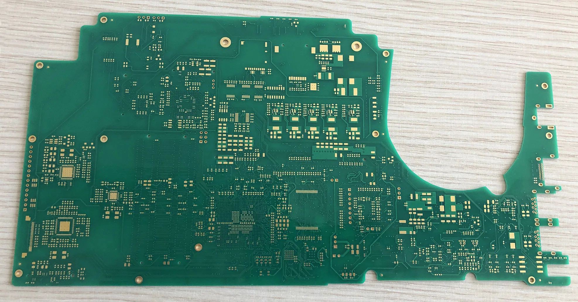
Top side of the dummy board. ![]()
Bottom side of the dummy board. The primary use of this dummy board is to perform mechanical checks in conjunction with the Slimbook notebook chassis. The board is not finished yet, the PCB designer still has to mount additional mechanical components such as connectors to ensure the final working prototypes will fit perfectly in the Slimbook Eclipse chassis.
The PCB designer in charge of the job is carefully working to fine tune the gerber design files and already adjusted some minor details, proving that a preliminary dummy board was very much needed.
We would like to thank Gerard Schneider that kindly offered us a ATI Radeon 7970 MXM card, it will surely help us testing the working prototypes that will be produced later on. We welcome anybody else willing to send us other Radeon MXM cards that may lay unused in a corner, we would like to start as soon as possible to test various GPUs in the upcoming working hardware.
[UPDATE 2021-04-22] Unfortunately our notebook board is set to work exclusively with MXM-A 3.0 (type A) with a size of 82mm x 70 mm and with a maximum power consumption of 55W, whereas the MXM card provided by that Gerard Schneider is an MXM-B (type B) with a size of 82mm x 105mm and a maximum power of 200W. Thank you anyway Gerard, your card will be useful to check and eventually fix the video drivers but it will not be used inside the prototypes.
Even if it is “just” a dummy board, this is a great milestone, and we are really happy about it because we can finally touch something with our hands. We would like to thank all the people that made it possible to reach this point, and we really hope that the donation campaign financing the final prototypes will speed up because now we all want to see more!!
Are you willing to help?
Being part of a project like this could be an amazing experience, you meet new people, volunteers of other projects, companies devoted to open source and everyone is willing to help. We are continuously giving examples of this in our blog posts but, in the last weeks, we are especially grateful about the support received from KiCad developers and Slimbook.
Two additional enclosures for our prototypes.
Slimbook is a company making a huge effort in promoting an Open Source environment. They produce notebooks, mini-PCs and desktop computers targeting mainly Linux users. As an example of their commitment to the open source community, they have a very have a good relationship with the KDE project and together they collaborate on the creation of laptops meant to use primarily KDE. Despite being a small company, they are having success selling their products worldwide and these are very appreciated by the Linux community. As you may know, we started our collaboration with Slimbook more than two years ago and they have been always quite helpful promptly responding to our requests and providing information about the enclosure design or the related components that will be also used in our notebook (screen, keyboard, dissipation devices, etc.). All their support and time was kindly offered for free. Besides that support, we have received two Slimbook Eclipse enclosures to continue our tests. This will make possible to assemble three prototypes of our PPC Notebook. Again, they did it for free. We have no words.
Export our PCB to KiCad, a difficult journey
At the very beginning of this adventure, we were trying to find hardware experts to design the motherboard but the level of expertise required for such type of hardware made this challenge unachievable for us. Of course, we have experts on that field but the complexity of this design demands quite a lot of time, impossible to carry out solely using the volunteers spare time. So we opted to look for a company experienced in motherboard design and even more difficult, a company that was experienced with the PowerPC architecture.
We were lucky enough to meet ACube Systems and its circle of collaborators. However, as most for-profit companies do, the ACube System subcontractor company had its own proprietary software tools which generates file encoded using non-open outputs formats. In our case we end up with files created using Mentor Xpedition, a software that cannot exporting to KiCad. To convert our Mentor Xpedition source files we were told to import them into Altium, and import the converted Altium files into KiCad.
Unfortunately, the KiCad importer for Altium files is still heavily under development, and it is far from being complete. We contacted the KiCad developers and they kindly accepted to perform some testing with our Altium PCB files and that helped spotting various errors in the conversion procedure. These error were identified by the developer in charge of the Altium import module for KiCad and he is currently addressing the encountered issues. Regarding the BOM (Bill Of Materials) the guys at KiCad recommended to import the Altium schematics to KiCad, and generate the BOM from there.
Obtaining an open source format for publishing our motherboard PCB is very important for us, as it allow anyone to easily access the result of our efforts to deliver a truly and fully compliant Open Hardware design.
After a few attempts, the guys at KiCad suggested another option: instead of converting the original Mentor Xpedition files to Altium, they suggested to load them using FabMaster. In fact, KiCad has another importer dedicated to FabMaster (for the board only) and the result of this import module should be useful to understand the level of accuracy of the Altium importer. In theory, the Altium import should produce better results with respects to the FabMaster importer as it is a newer. We are currently investigating if we can follow this path, as it seems to require a full Xpedition license, therefore we are in the process of contacting the subcontractor engineer to explore this solution.
An AmigaOS4 AHI driver for our sound chipset
Our notebook motherboard is open to any operating system supporting PowerPC. Among the operating system that could possibly work, there is AmigaOS 4, a closed-source system that already works on the E-AON AmigaOne X5000 that mount either a NXP P5020 or a P5040, which are both PowerPC Book3e e5500 CPUs. These CPUs can be considered the previous generation CPUs with respect to our T2080 (PowerPC Book3e e6500), one of the main differences is that they lack the Altivec unit, which the T2080 has.
On the April 1st the Dutch developer H. Kanning (nickname “geen_naam”) announced the availability of an AHI sound driver supporting HD Audio compliant chips, and explicitly supporting the C-MEDIA C8828 that we selected for our motherboard. At first we though it was an April fool, but then it was confirmed to actually exists and work, meaning that another operating system is one step closer to being supported. Great job!
-
PCB Complete sources published! Mentor Expedition, Altium and Kicad formats
04/10/2021 at 13:33 • 0 commentsAt the beginning of March the consultant engineer paid using the donation campaign provided us with the Mentor Xpedition source files of our PCB. Providing source files created with a proprietary software is not ideal, therefore we have worked to convert the sources to the Open Source KiCad format.
To achieve the porting of the sources, we first tried loading the Mentor Xpedition sources using the PCB Design Software Altium, and from there, export the sources to KiCad.
We were pleasantly surprised by members of the KiCad team that promptly answered our call for volunteers able to help us in the source translation process, thank you guys, it was really much appreciated!
In our task, we found a very useful post on the KiCad blog that explains how to import an Altium PCB design file in Kicad.
Apparently the Altium Importer is not available if you start PCB window from the KiCad project manager window, you have to start it from the command line as pcbnew-nightly to get the KiCad import feature for loading alien formats.
KiCad eeschema-nightly currently does not support importing Altium schematics. There is an ongoing discussion, so perhaps there are some alpha/beta-testers of it.
![]()
For BOM – we are finding information in the Altium database as well as KiCad. The KiCad export info we obtained in our first attempt is simplistic, and it does miss instance identifiers (c43, u17, r9 sorts of designators, which are present in Altium info). We do not see anything yet about enabling/disabling details types from the KiCad BOM export, so we are unsure whether more detailed columns can be obtained.
![]()
You may find the original Mentor Expedition sources in our GitLab repository. We were unable to run the visECAD Viewer as even the provided free license version doesn’t seem to work. In fact, visECAD Viewer appears to be withdrawn from the market and it not anymore available to download, and we did not not receive any answer to our requests of support from the Siemens team.
We were able to view the Altium import with the Altium online viewer thanks to the support of the Altium team.
After all our attempts, we are now pleased to announce that it is now possible to load the source files of the notebook motherboard PCB in KiCad using its kicad-nightly version.
Another recent news about the PowerPC notebook project, is that Slimbook will kindly provide us with two additional Slimbook Eclipse empty chassis. These will be used to test that our prototypes will correctly fit. At the same time, the guys at ACube Systems are investigating suitable MXM video cards mounting AMD chips that could be used in the prototypes. We are investigating how we could collect the additional funding required to pay for the various MXM video cards that will be used for testing and for the two additional Slimbook Eclipse chassis.Thanks to the kind contribution of the donors, the preparation of all components for the prototypes is progressing well.
We would like to reach the 50% of the final goal of the current campaign as soon as possible to avoid slowdowns in the current prototypes production phase. We currently need your financial support more than ever!
-
PCB gerber files published, Updates on the Prototypes
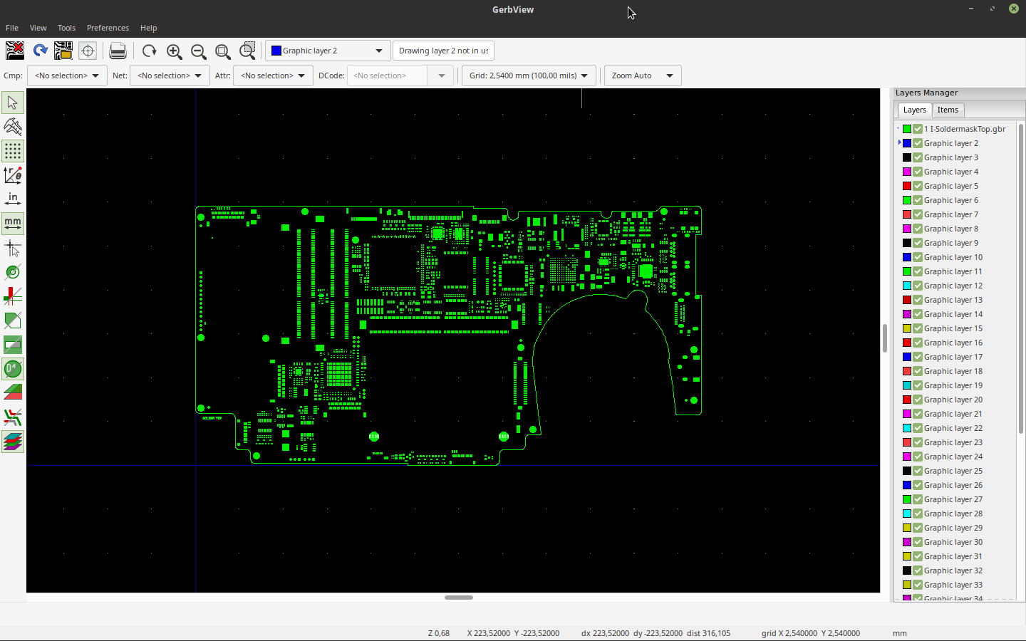
02/14/2021 at 11:59 • 0 commentsWe have published the first version of the gerber files of the notebook motherboard PCB on our GitLab repository!
![]()
The engineers in charge of the design used the software Mentor Xpedition to carry out the design, and in a couple of weeks we will publish their original sources of the PCB from which the gerber files were exported. The cause of the delay in the publication of the sources is because the PCB simulations still are being performed, and until then the sources -and consequently the gerber files- might change. The simulation of the PCB that was successfully financed with the previous donation campaign is currently being finalized. As nobody in our association has the required tools, ACube Systems is taking care of supervising the entire review process for us.
![]()
We are perfectly aware that providing source files created with proprietary software is not ideal, therefore we are investigating how we could provide the PCB sources for the Open Source KiCad software. A first attempt we are testing is to load the Mentor Xpedition sources using the PCB Design Software Altium, and from there, convert the source to Kicad. We are looking for volunteers that could help us in the source translation process.
While interacting with ACube on the simulation process, we were faced with the fact that the verbal agreement we made on the prototyping costs dated back to mid-2017 and the world went through great changes. Back then, they estimated a total cost of €10.500, consisting of a first € 3000 for the initial equipment, and € 1500 for each prototype motherboard, multiplied by 5 motherboards. However, after detailing and updating all involved costs using today’s market quotations, it appears clear that most of the components costs have increased since then, maybe because of the pandemic, who knows. Take for example the NXP T2080 CPU, since 2017 its price has simply dubled, and most of the other components have increased their price too. We discussed extensively with ACube Systems, the initial equipment is still € 3000, but the final cost of each prototype motherboard has increased to € 3000, doubling the initially estimated price of 4 years ago.
![]()
Because of this dramatic increase in the production cost we decided to make 3 working prototypes only, that makes € 9000. On top of these we add another € 500 to make a dummy board (not working board), printed with a two layers PCB and all mechanical components correctly mounted. The scope of such a dummy board is to ensure that the working prototypes that will be produced later will mechanically fit in the Slimbook Eclipse. As a result, the ongoing campaign goal will be increased to € 12.500
![Slimbook Eclipse Notebook]()
Donation Campaign for Production of three working Prototypes
We are currently investigating the impact of the increased production costs to the final product, but we do not have an answer so far. We will keep you informed as soon as we have a reliable estimation.
OSHW GNU/Linux PowerPC Notebook
Open Source Hardware GNU/Linux PowerPC Notebook project