 ptrav
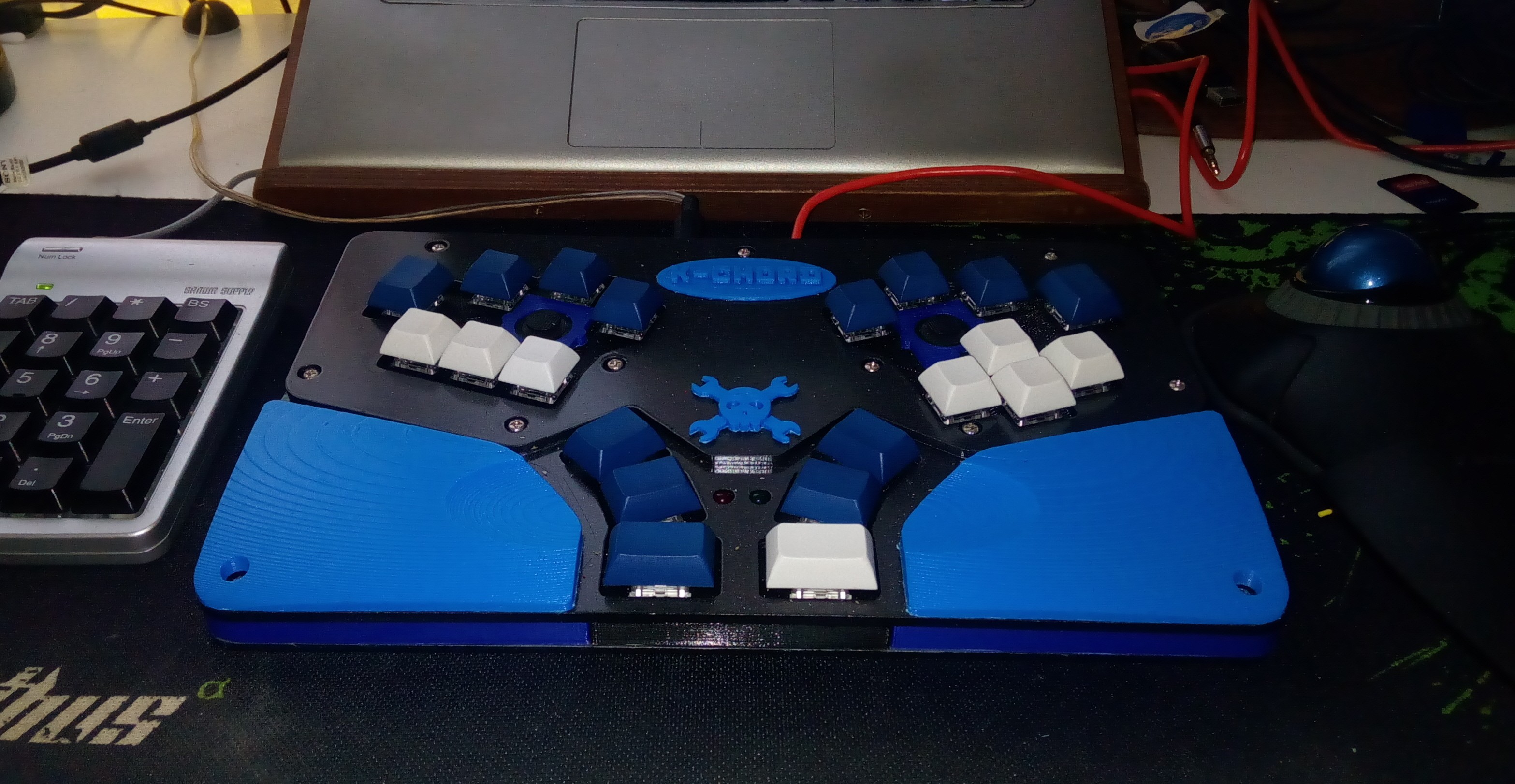
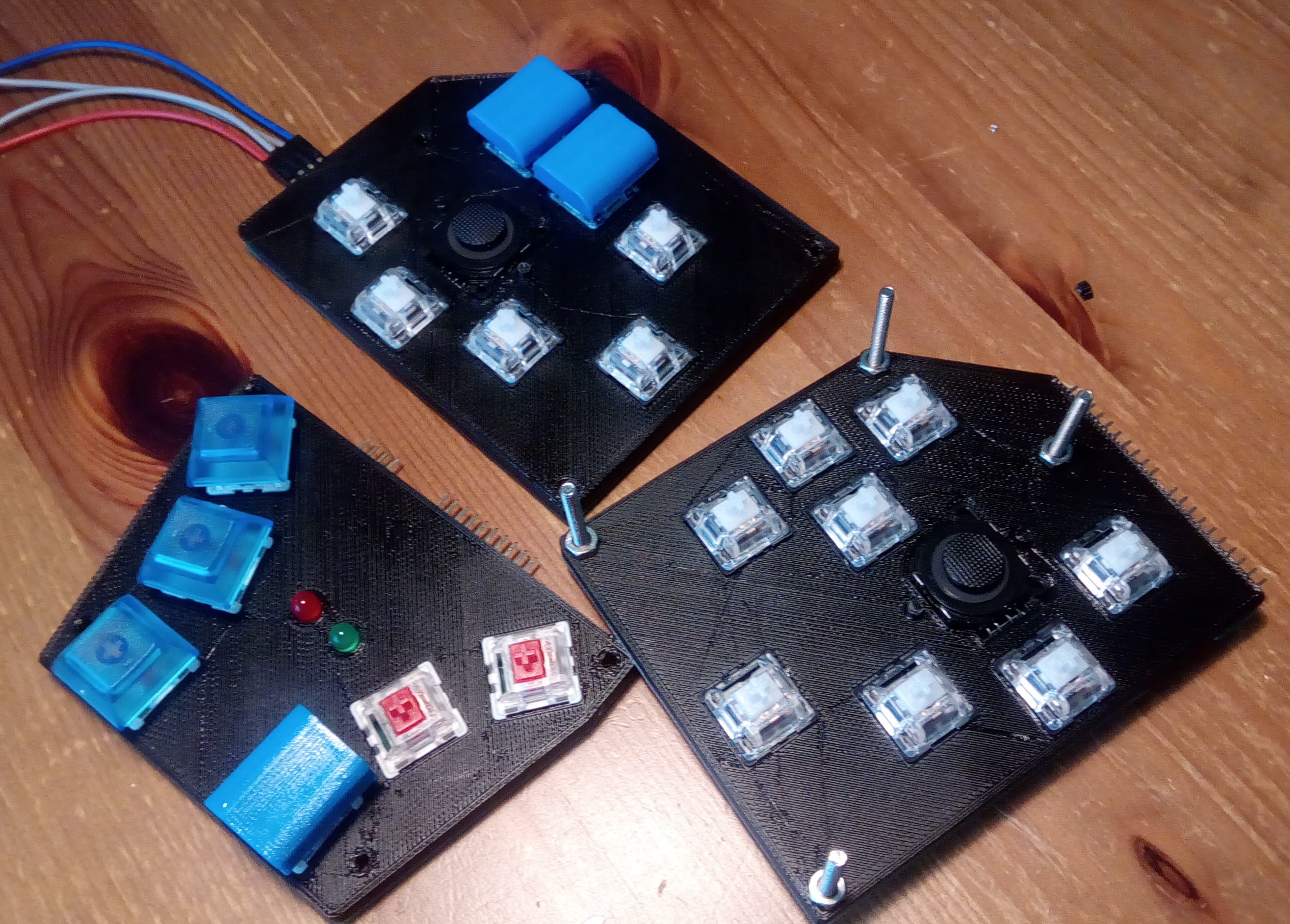
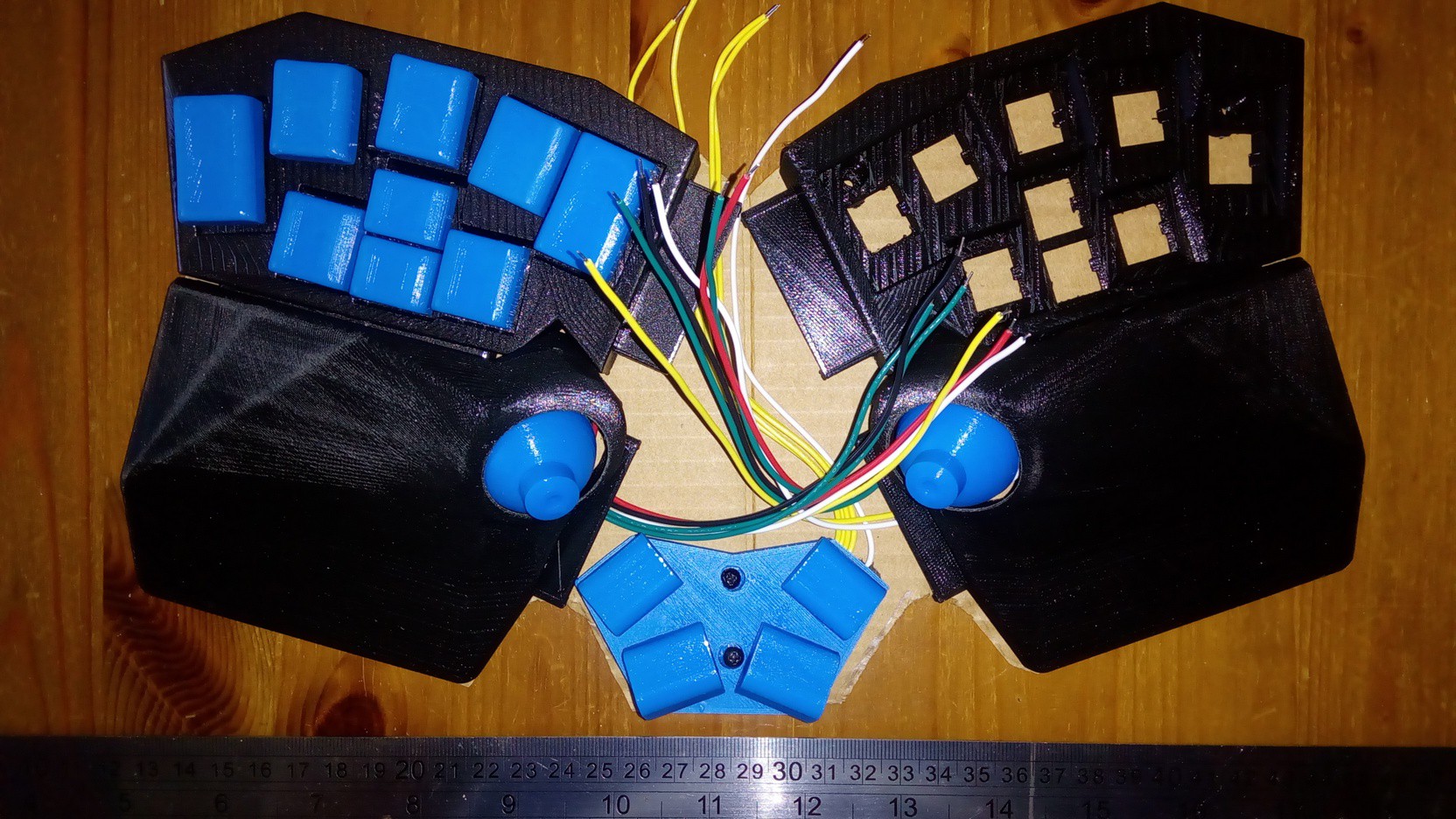
ptravThe keycaps' shape is inspired by Andrey Kalmatskiy project "32xe".
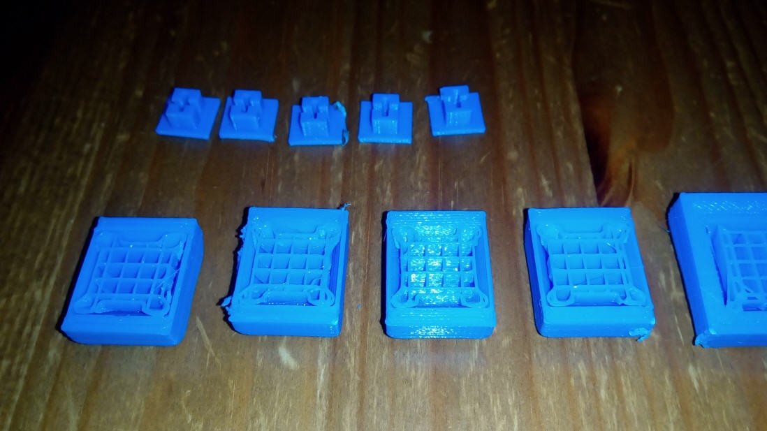
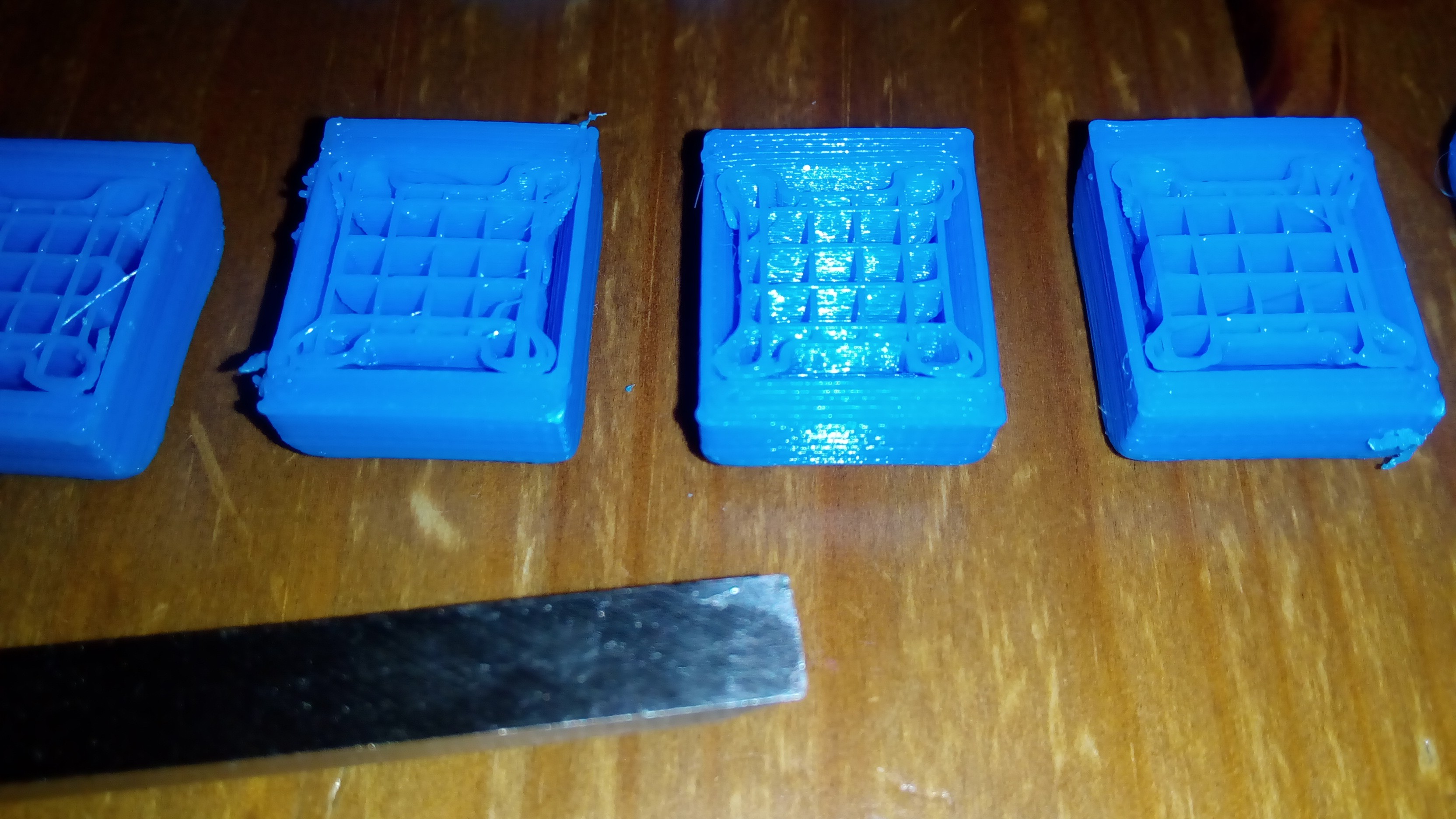
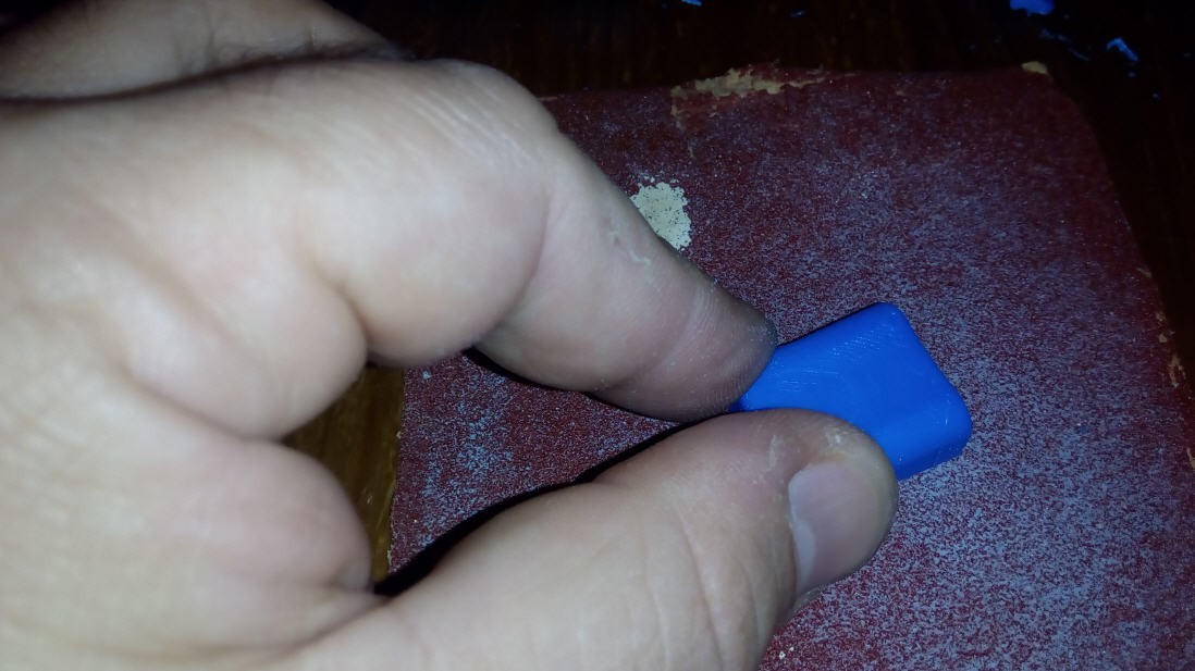
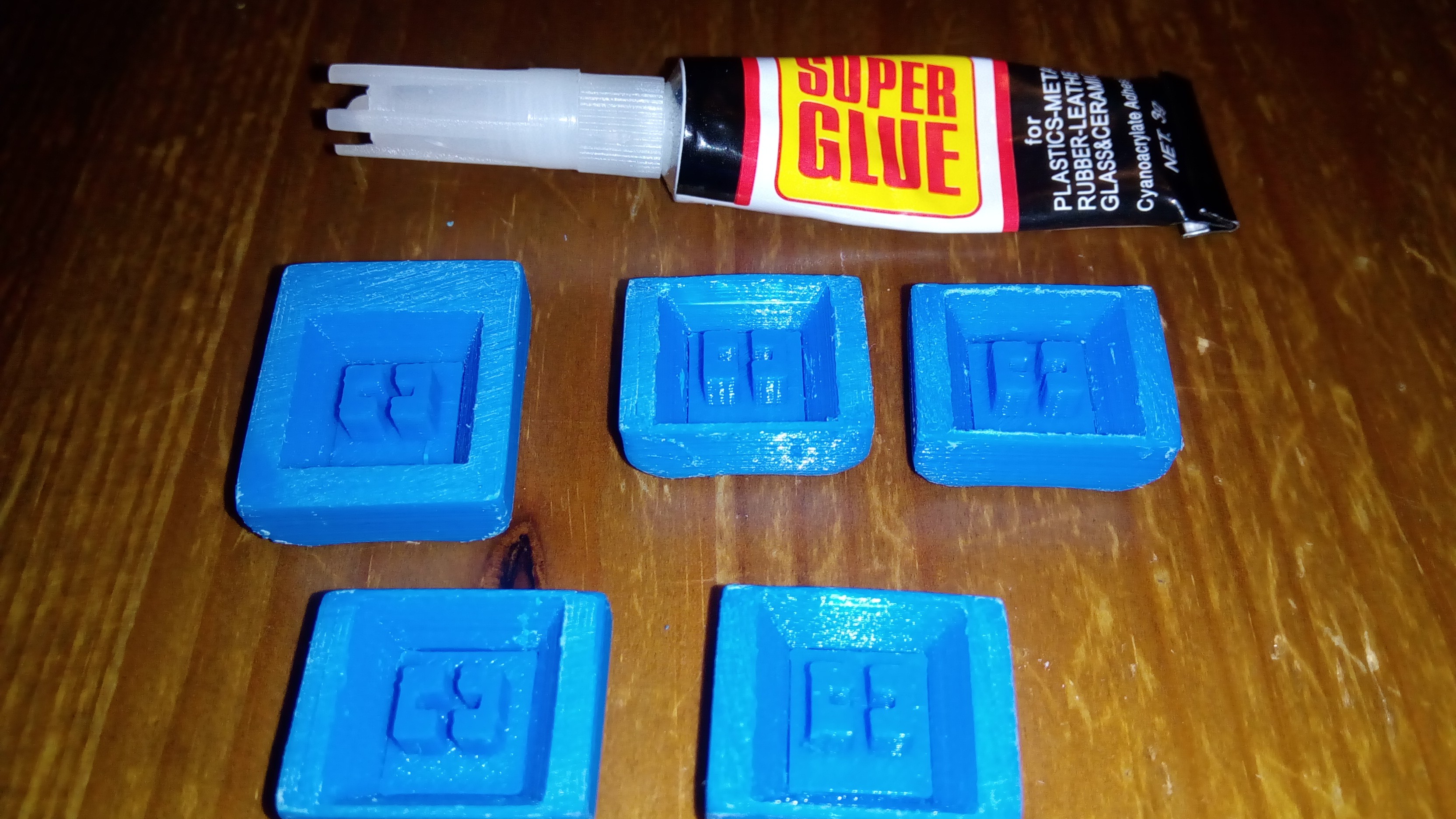
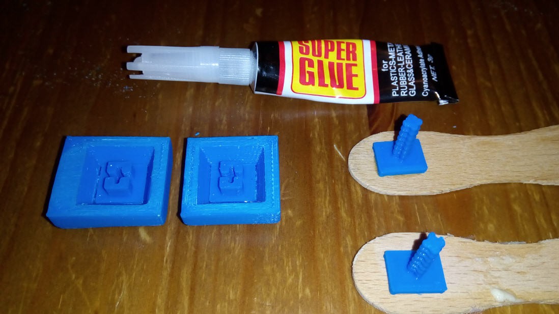
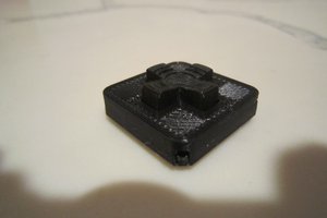
Not everyone can print rinse-away support structures, so for the best printing results and ease of post-processing the stems were separated from the tops. Each cap can be freed from the support structure with just two moves of a 6-mm wood chisel, then the stem is glued in place with a drop of Superglue.
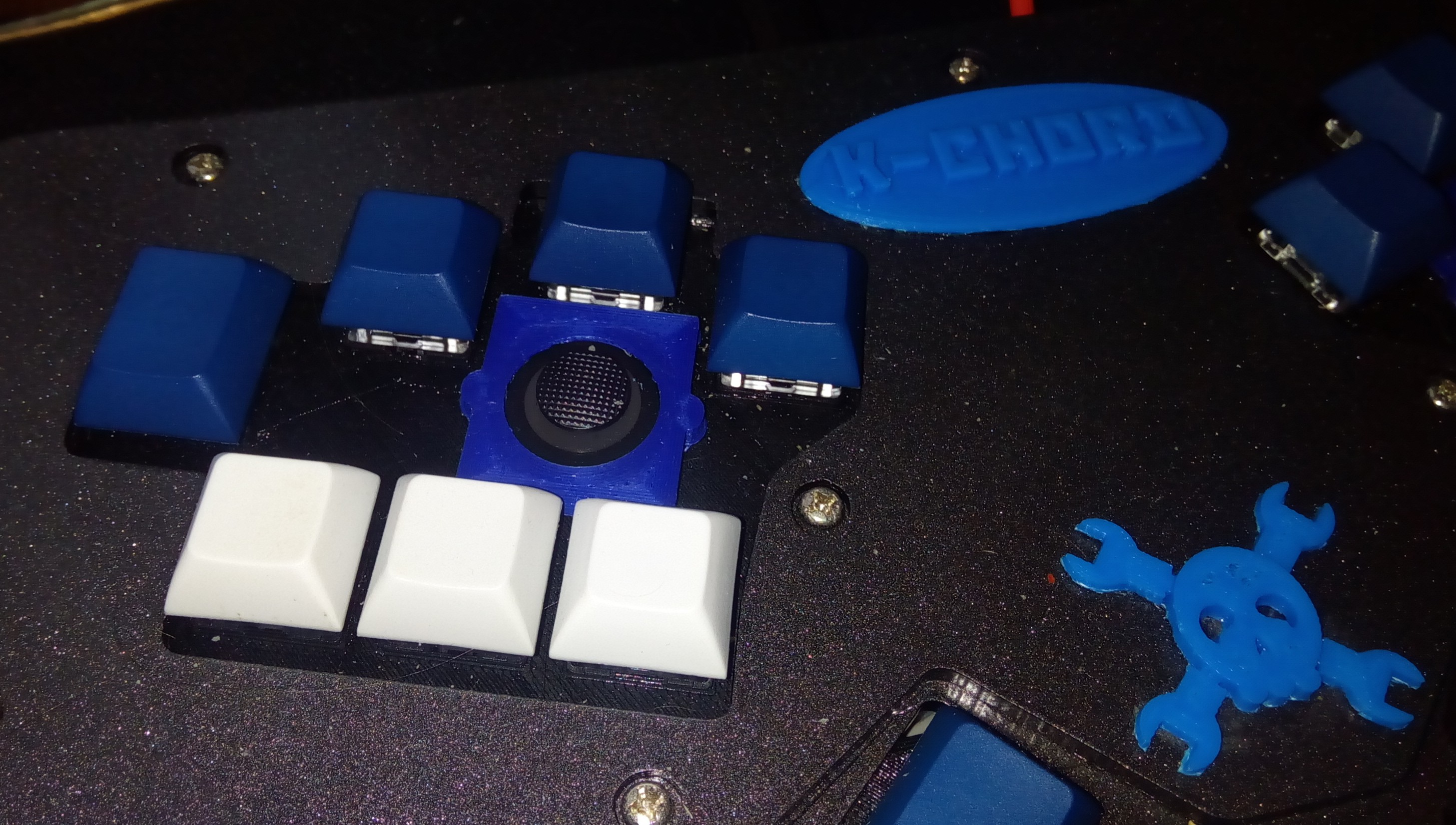
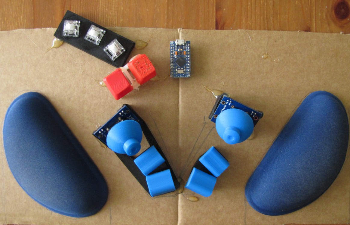
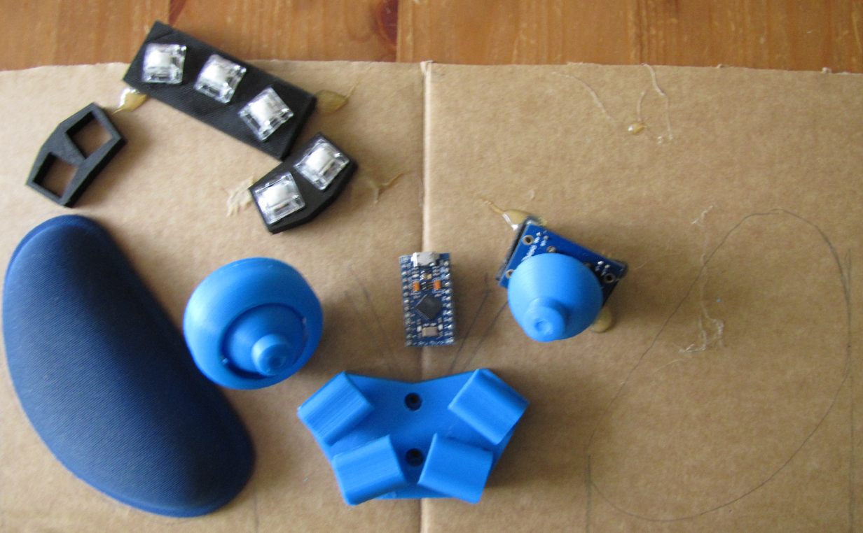
For the buttons and the joystick caps, 0.1 mm step is used. With my printer, I saw no significant improvement by moving to 0.06 mm step, at the price of making the prints slower (and probably less robust).


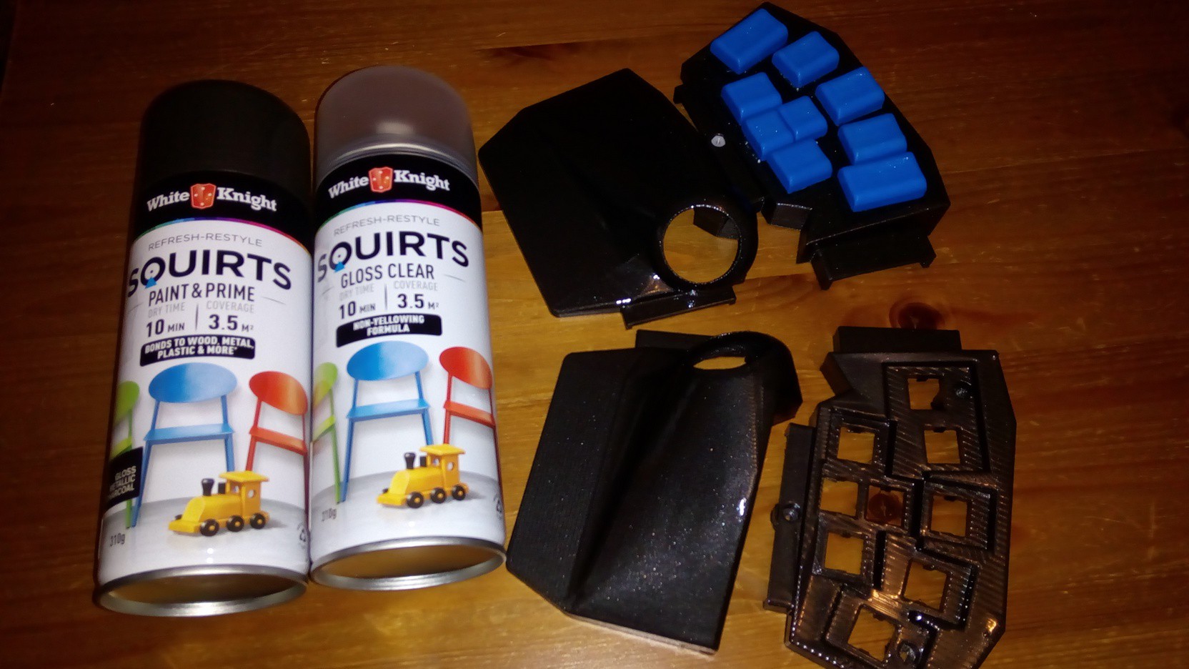
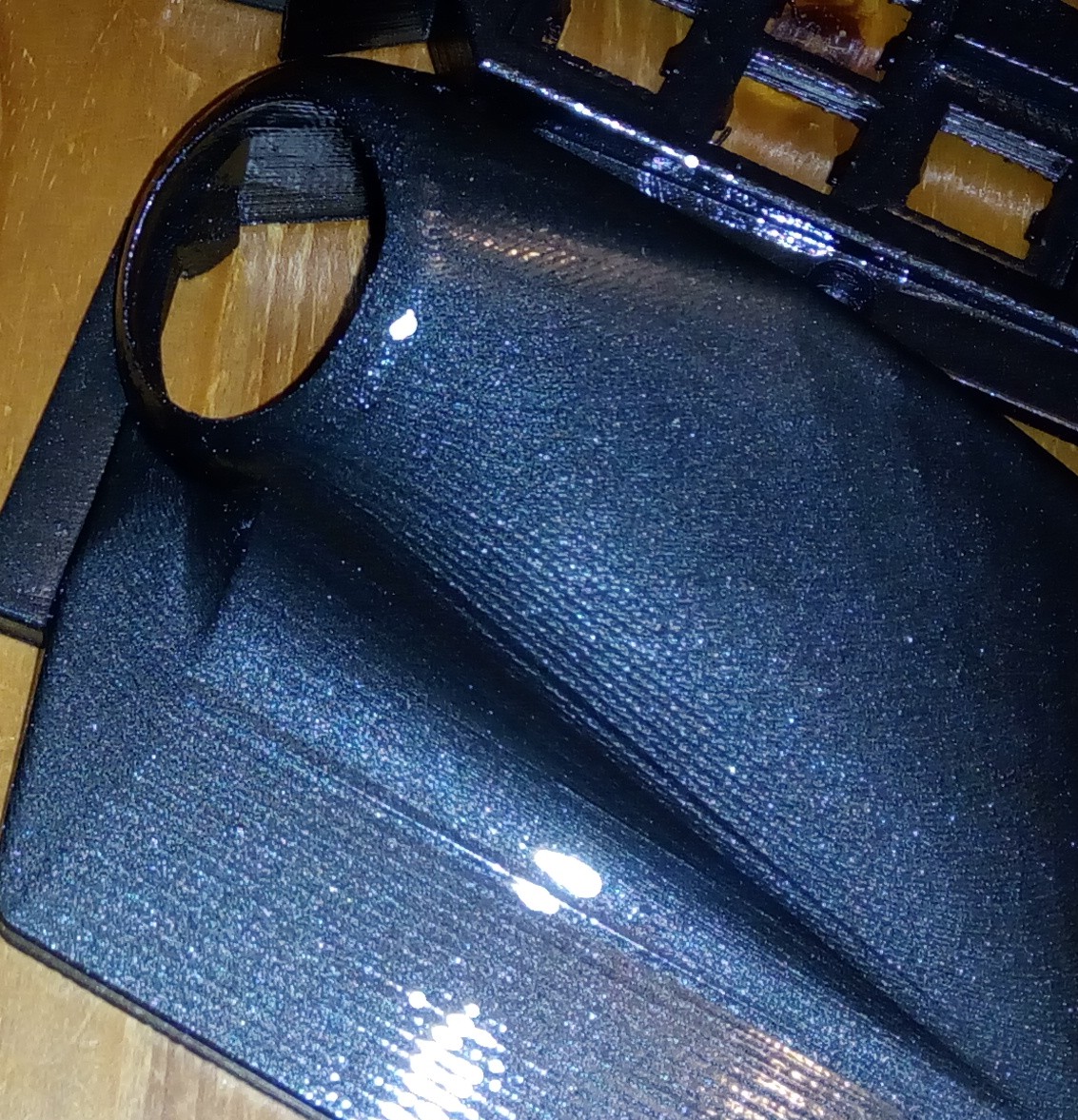
 6. Spray paint. I used 3 layers of transparent coating.
 rand3289
 M. Bindhammer
 Beko Pharm
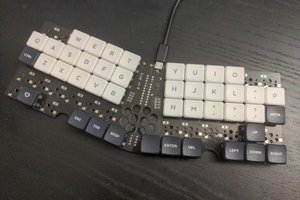
 deʃhipu