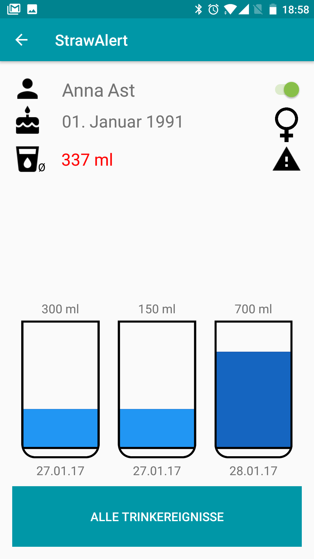
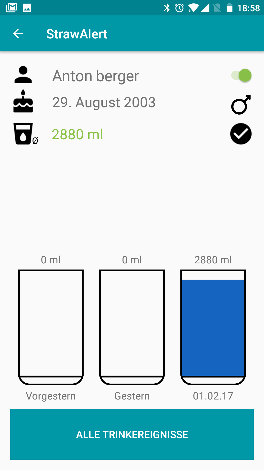
Close
0%
0%

HydrObserve - stopping dehydration deaths

An automated system that helps the elderly to stay hydrated and therefore prevents hospitalizations and deaths. Saving millions $.

Similar projects worth following
HydrObserve is a system that automates the task of liquid intake monitoring for the elderly.
A modular sensor device measures a drunk volume of liquid reliably and transfers the data automatically to a smartphone or tablet.
Here, warnings pop up in an app (if hydration is low), the data is visualized and sent to an online database for automatic documentation.

Dehydration, the lack of water within the human body, is a serious issue for the elderly. In Germany alone, it was diagnosed 100.764 times in 2015, causing thousands of deaths and over 275 millions of direct healthcare spendings.

The good thing is, that dehydration is absolutely preventable. HydrObserve aims to investigate a possible solution.

The device is compact, usable, affordable, modular, robust, exact and low power!

You don’t drink? You die!

Dehydration (the lack of water within the body) is a serious threat. You may feel thirsty if your body wants to get hydrated, but your grandma probably doesn’t. As the feeling of thirst decreases with age, the need of water intake rises, due to reduced kidney functionality and more medication which needs to get washed out of the body. High demand of water with low liquid intake = problem. In in 2015, in Germany alone 100.764 people, mostly older than 70, got hospitalized with the primary diagnosis “acute dehydration”, leading to direct costs of more than 275 mio. € for the health system. Not speaking of the > 5000 deaths, and all the suffering and costs related to the possible implications of dehydration: paradox diarrhea, fall, cardiovascular diseases, kidney malfunction.

Why doesn’t anybody do something against dehydration?
Well, people do. Risk patients are monitored with a so-called hydration protocols, a table where the nurse notes down the volume of drinks given to the person of concern, a daily sum is calculated and – if too little was drunk – alarms are raised.

The problem with this approach: it takes the nurse some minutes every day. Time in nursing homes is expensive, and for that reason hydration-protocols are usually not applied in all, but only few cases of higher risk. But it is not these high-risk cases, which result in all these deaths and millions of costs. It’s the sum of those individuals, who are not monitored.


Solving the problem by automation

If in the current state of care liquid intake is not monitored because of the additional time needed for this task, then there is the need to automate fluid intake monitoring.

In other words: we want to minimize the time of human interaction needed for this task. Today, human interaction is needed in two major categories of liquid intake monitoring:

  • Measurement of volume: the caregiver estimates/measures the content of a cup and note it down on a piece of paper.
  • Evaluation and documentation: end of the day, the caregiver manually sums up all registered volumes, decides if hydration is sufficient and files the table which was used for documentation.

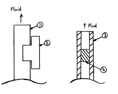
-> We need a sensor device, that automatically measures the drunk volume. To reduce errors (e.g. spilling), it would be best to do so as close to the process of drinking as possible.

-> The measured data should be analyzed and processed automatically. The human should only be needed to act if the hydration level is low.

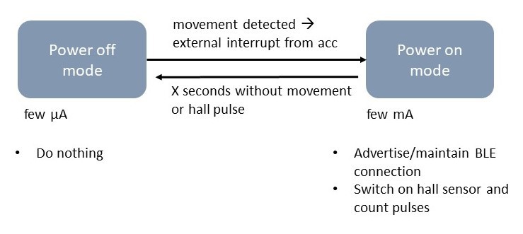
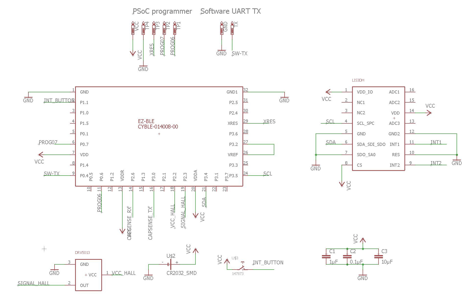
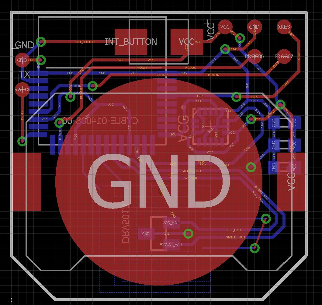
With these two points and the requirements in mind, the following architecture seems legit:
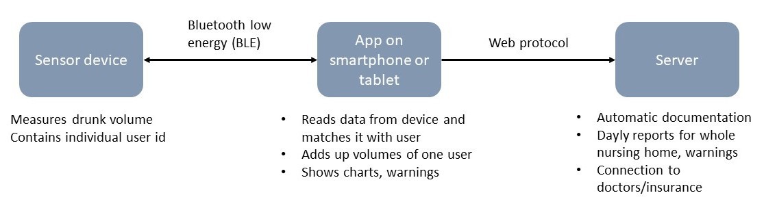

Intended way of use

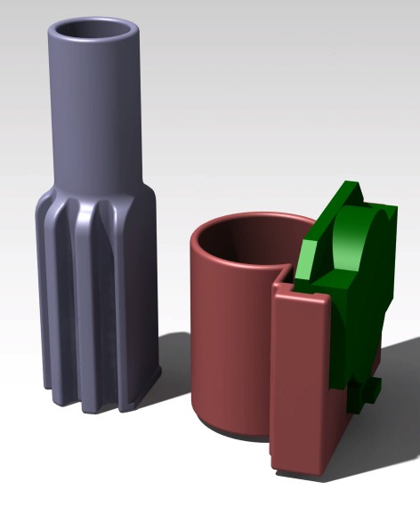
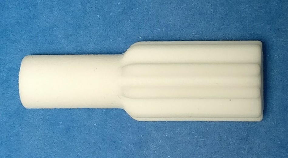
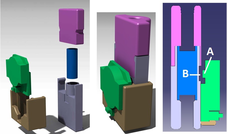
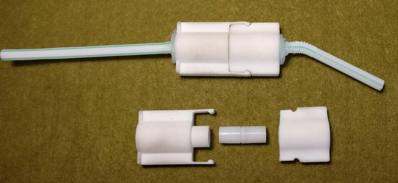
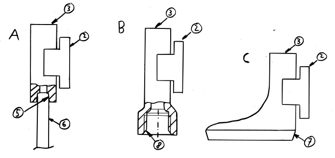
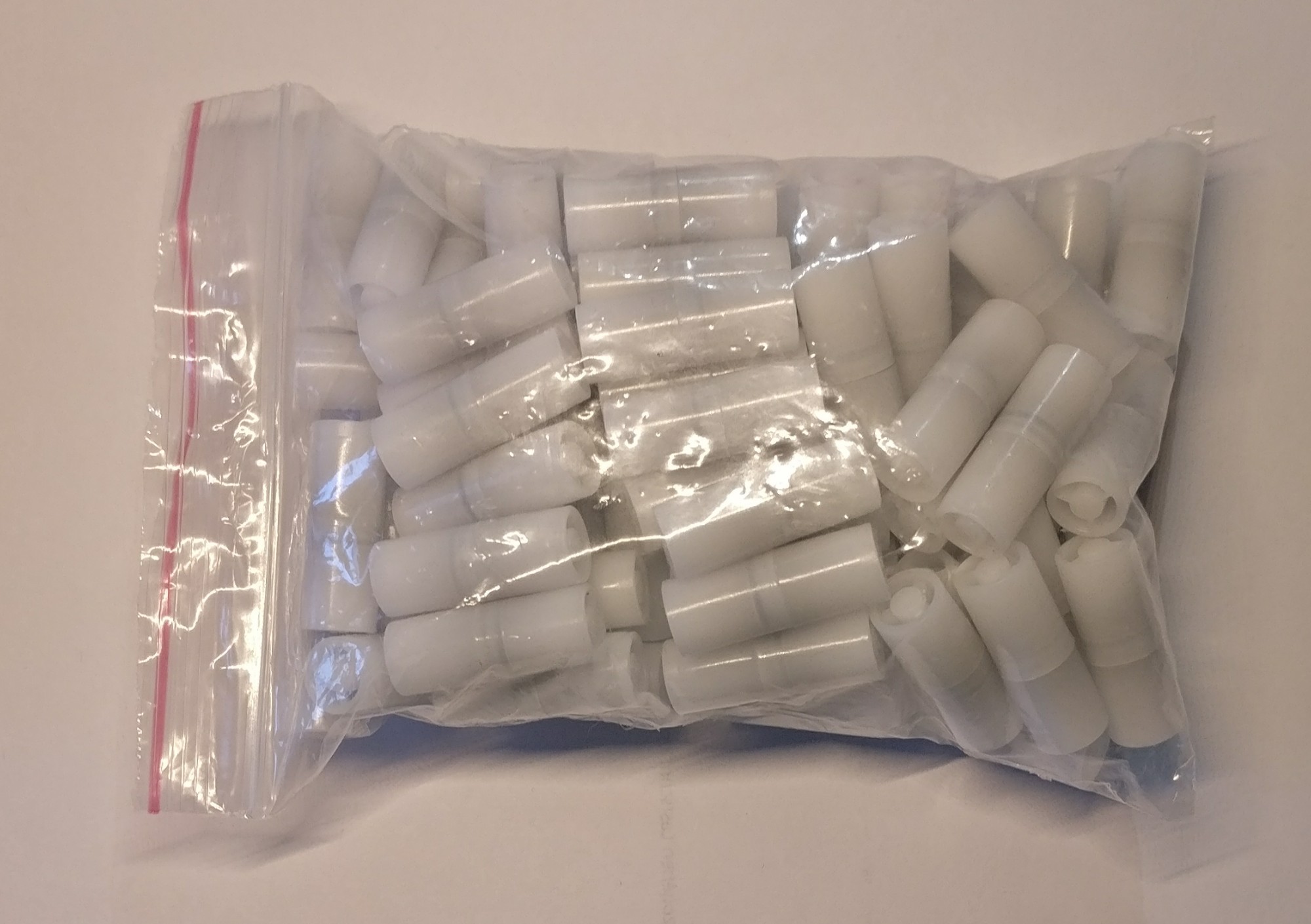
  1.  When preparing drinks, the caregiver in the nursing home fits a suitable version of the mouthpiece to the drinking container. The mouthpiece comes in different forms: e.g. the tip for a regular straw, the lid of a feeding cup or the screw cap for a coke bottle.
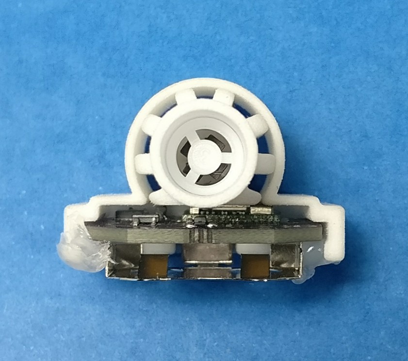
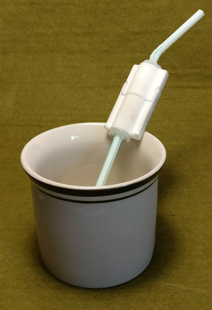
  2. When handed the drink, the individual clicks in her/his personal sensor unit. Now, the assembly measures the volume he/she drinks and saves the value within the sensor unit.
  3. When finished, the sensor unit is detached from the mouthpiece and remains at the individual. The mouthpiece is collected and put into the dishwasher, with many others.
  4. In the end of the day, a nurse walks by with a phone or tablet, which automatically collects all the data saved on the sensor units, pops up warnings if neccessary and hands over the data for automatic documentation
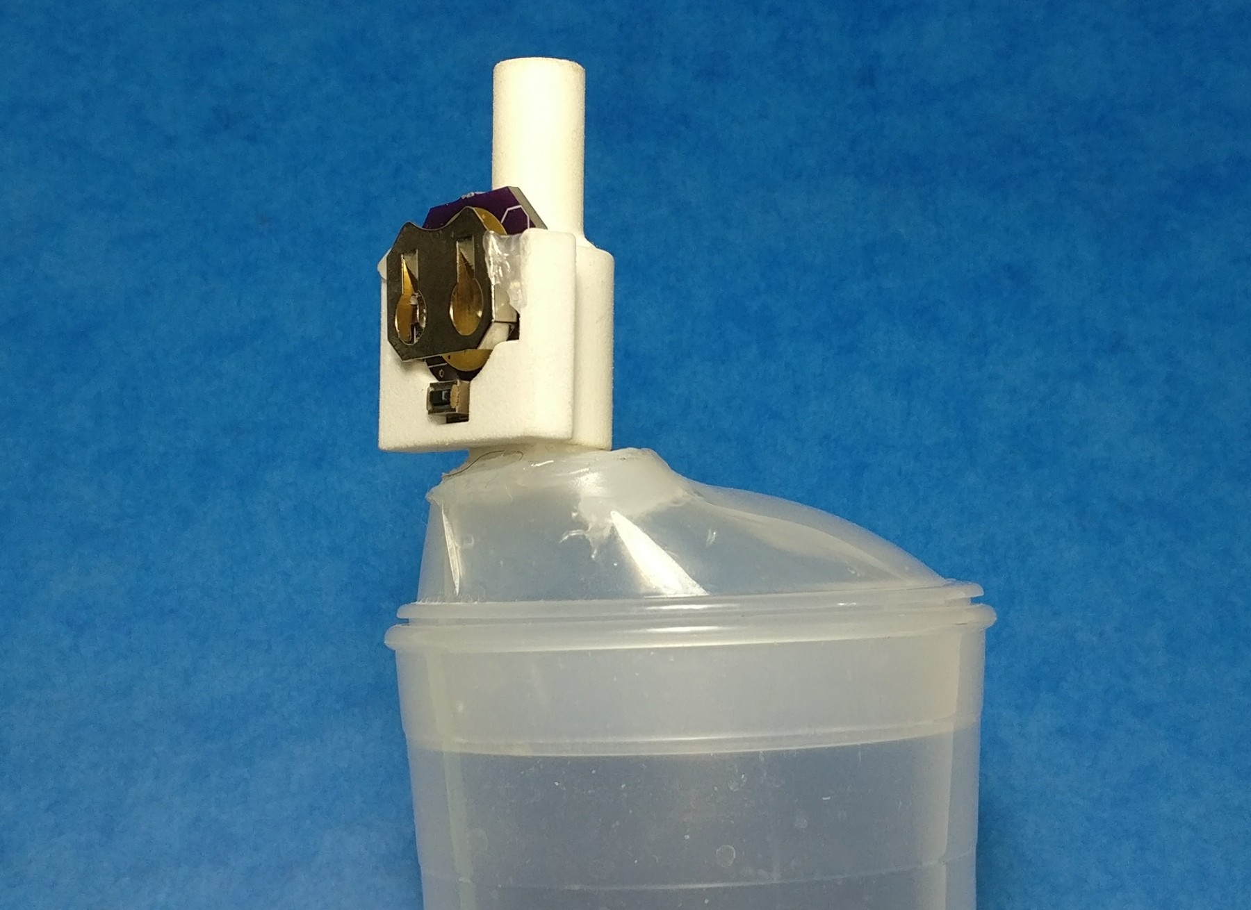
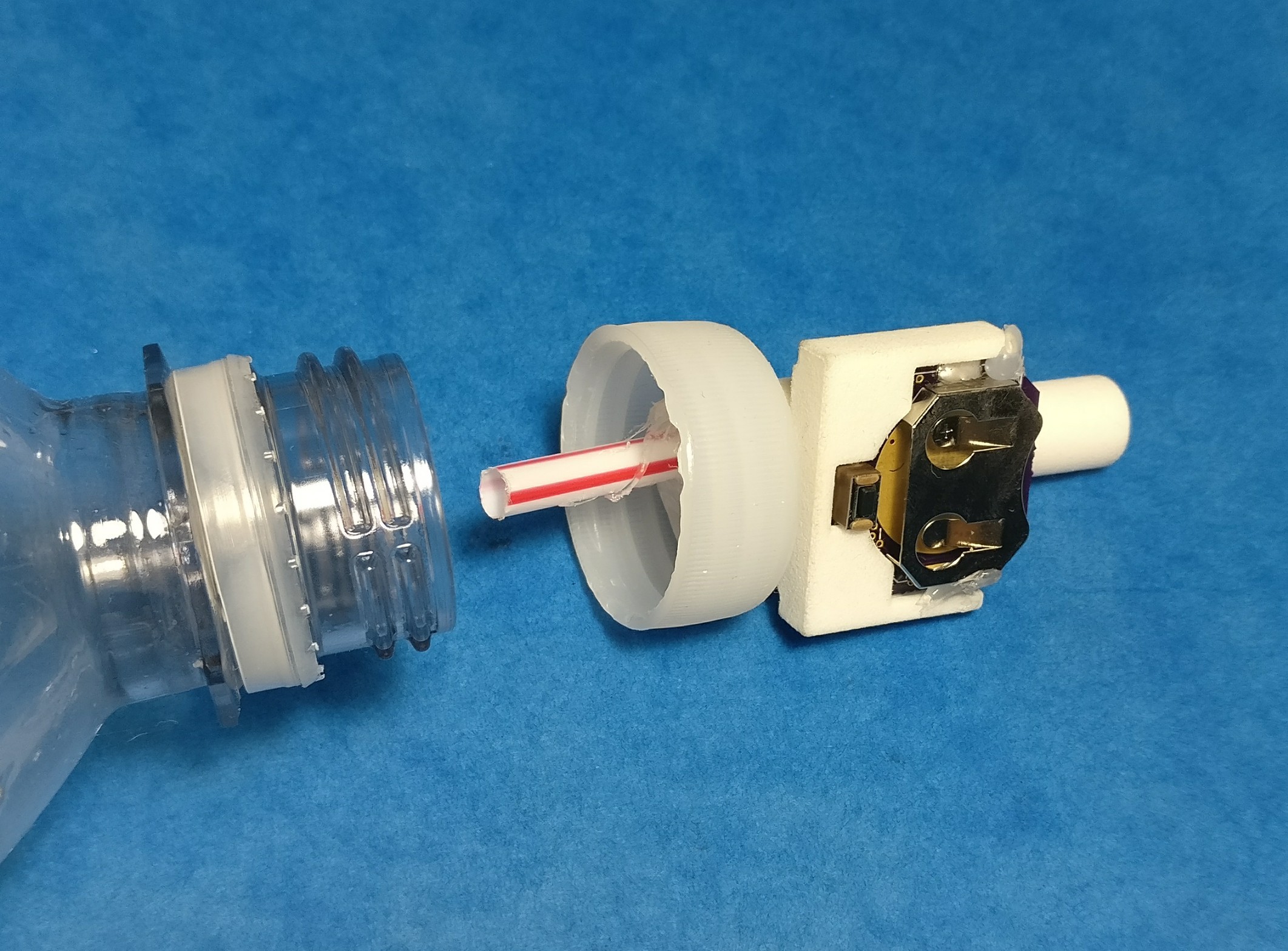
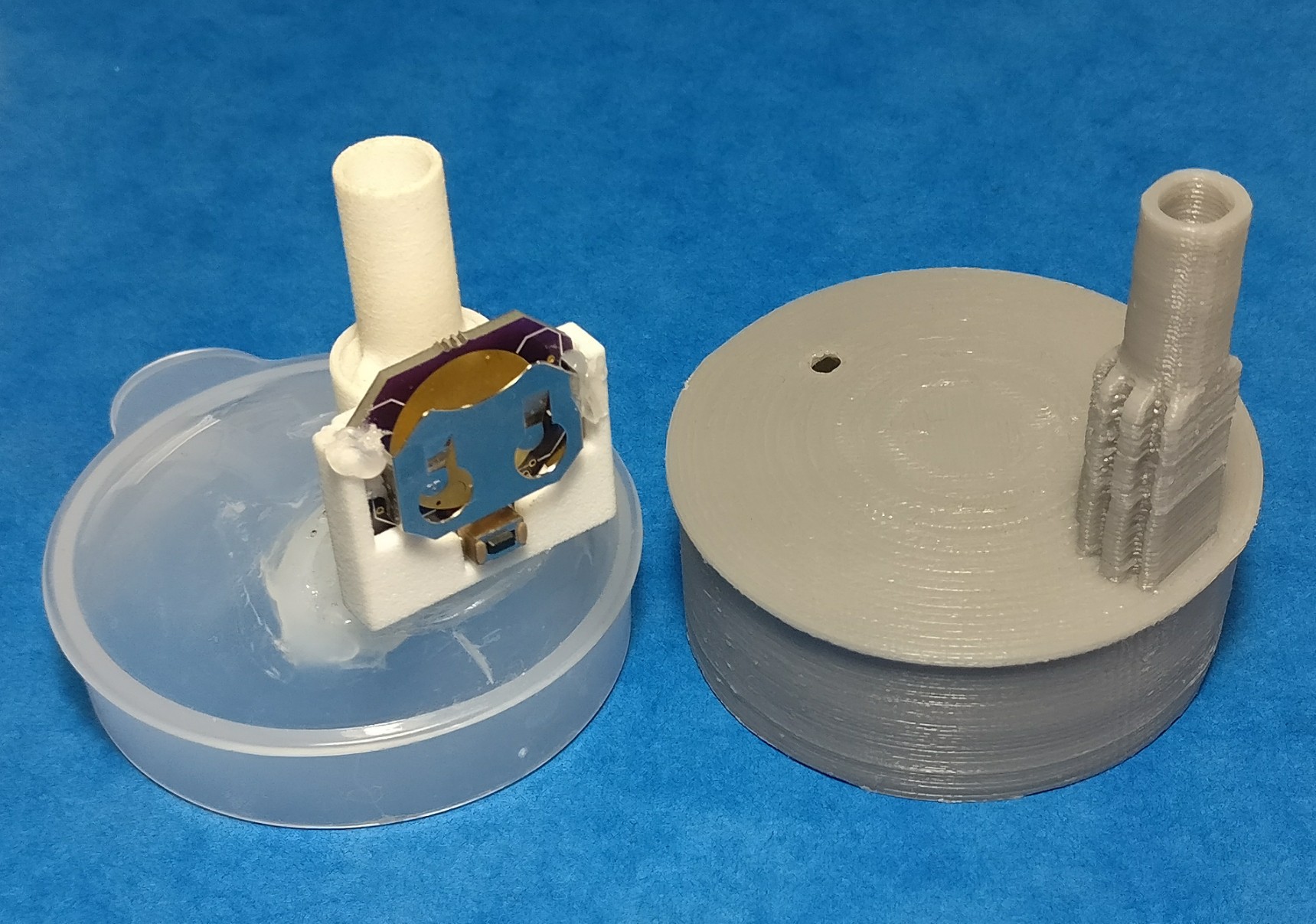
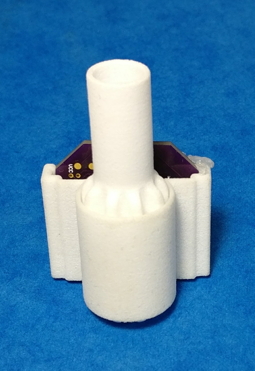
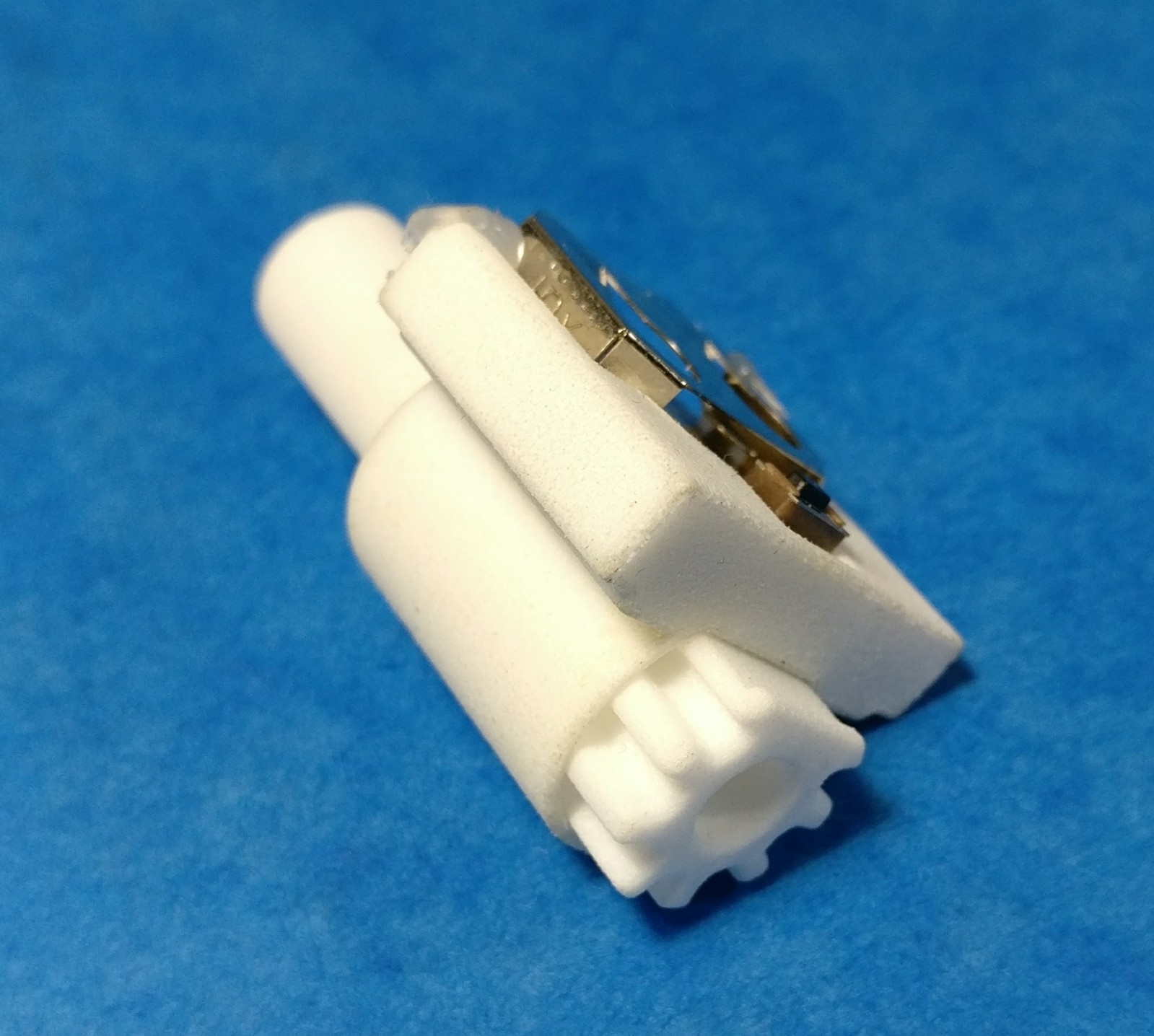
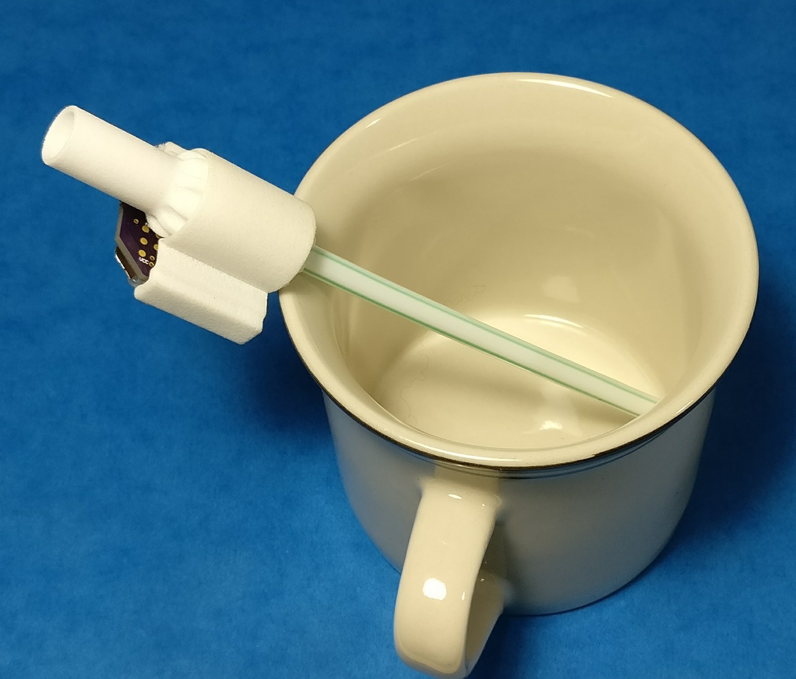
Example of use: mouthpiece (1) with attached sensor unit  (2) mounted on a regular straw

Additional requirements

  • Compact: The sensor device is small enough to be added to everyday drinking equipment
  • Usable: everybody’s grandma should be able to use the device.
  • Affordable: no expensive medTech product. Affordable for everyone!
  • Modular: the device is not be limited to only one cup or bottle. It is possible to use it with the different containers we use when drinking every day.
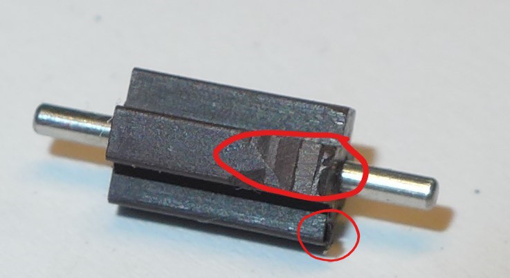
  • Robust: the...
Read more »

BLE_spec_v1.xlsx

Specification of the BLE Services and Characteristcs of the device. Use this if you want to interface with it or build your own app

sheet - 10.30 kB - 08/31/2017 at 17:44

Download

StrawAlert_26.08.2017_15.11.apk

Demo app for android. See log 10 for discription

Android Package Archive - 1.98 MB - 08/31/2017 at 17:41

Download

mouthpiece feeding cup lid.stl

The 3D printable mouthpiece in form of a feeding cup

Standard Tesselated Geometry - 4.49 MB - 08/28/2017 at 08:36

Download

hydobserve_pcb.sch

EAGLE files for pcb

sch - 229.75 kB - 08/27/2017 at 16:47

Download

hydobserve_pcb.brd

EAGLE files for pcb

brd - 80.89 kB - 08/27/2017 at 16:47

Download

View all 7 files

  • 1 × Mouthpiece 3D printed piece of plastic. STL in downloads
  • 1 × clip/holding bracket 3D printed piece of plastic. STL in downloads
  • 1 × PCB eagle files are in downloads.
  • 1 × EZ-BLE PSOC module Mouser-ID: 727-CYBLE-014008-00
  • 1 × Low power acellerometer Mouser-ID: 511-LIS3DHTR

View all 9 components

  • Demo app for android

    jflaschberger08/31/2017 at 16:10 0 comments

    So far, we only dealt with the Hydrowarn device itself. The real power and one key requirement is automation. And where is the automation, if you have to read out the BLE charateristics maually? Jup, we need an app to do this for us.

    BLE characteristics documentation

    I'll not explain how BLE in general works, one can find nice sources for this online.

    In the download section of this Project, you find a pdf with all characteristics, UUIDs, value ranges etc. so that you can build your own app or retrieve the data using a BLE dongle.

    Demo app

    The app (unfortunately in German) was programmed by a friend to demonstrate how HydroWarn can be used. the APK file kann be found in the download section. If you work with android studio, you can access all source through github.

    I'll explain the fuctionality along the workflow, that a caretaker using the app would follow:

    1. Start App and login: When starting the app, you have to log in with "Admin", both for user and password.

    2. Register new patient

    If a new HydroWarn device is registered to a patient, it is done as follows: the caretaker taps on the plus symbol in the main screen and the following window openes.

    Name, birthday and gender are entered and with a tap on "Registrieren", the app is searching for a HydroWarn to be registered to the user. The button of the device is pressed, app and device connect - that's it. A success message confirms.
    For each patient, a unique ID is generated from name and date of birth, so one patient can have multiple HydroWarn devices registered to her/him.

    3. Bring phone/tablet in BLE reach and read out HydroWarn modules

    Once a day, the caretaker would go into a room with one or multiple HydroWarn units, then pressing their buttons or slightly moving them to wake them up. The devices will automatically connect to the app and send the volumes of liquid that has been stored since the last readout and match it to the right person in the database.

    4. Check if all HydroWarns have been read

    On the main screen, the section "ausstehend" show all users, for whom no volume data has been collected within the last 20 hours. If there are persons indicated, the caretaker would then make sure that this person's HydroWarn is also read out.

    5. Check potentially dehydrated patients

    In the section "Auffällig" in the main screen, all those patients are displayed, who have drunken less than 1.5 liters at the last data read out. 

    With a tap on the patient, the individual profile is shown. One can see (with the warning symbol), that only 337 ml were registered at the last readout. Now the caretaker would see the person and check if liquid was spilled, HydroWarn wasn't properly used and in case provide hydration.

    In the section "Alle" in the main screen, all person's profile can be seen. The following example of Anton Berger shows a last readout of 2880ml, so enough hydration.
    For each profile, the radio button next to the name defines, if the person is "active", so warnings pop up if no sufficient hydration is detected or not. This way, persons can be deactivated if on holiday or in hospital.
    A tap on "Alle Trinkereignisse" shows a list of all data readouts for the person.

    6. Sync with database

    Of course, the app is connected. Here it is only a dummy, but the code already is pre-written. With this action, documentation is a piece of cake!

    7. Logout

    Because the aquired data is somehow personal, the caretaker would tab on the off-symbol in the top right of the main screen to log out and end the app.

  • Prototyping different mouthpieces

    jflaschberger08/28/2017 at 08:31 0 comments

    So far, we have only played with the straw-attached version of the mouthpiece. The “modular architecture” of the device which we defined in earlier build logs allows for much more, though!

    Let’s think about which types of drinking containers might be used or are easily adoptable within elderly care. It will be mostly:

    • Glasses, cups --> straw attachement, already done
    • Feeding cups --> lid for feeding cup
    • Standard plastic bottles --> lid for bottle screw caps

    Prototyping the latter two with the existing mouthpiece and a bit of hot glue results in two new, usable versions of the mouthpiece!

    Module hotglued onto a feeding cup lid. Beatification still possible, but it works.

    Module hotglued onto an ordinary srew cap. To let air access the bottle when drinking, there is a small hole in the cap. The short piece of straw guides the air a bit into the buttle, so that it isn't sucked out immediatly when drinking.

    Enabling full potential: injection molding parts

    Haha, good joke. We are not actually injection molding here. Never the less, instead of abusing and hotglueing different parts of plastic, the different mouthpieces COULD be injection molded as one integrated part. The only assembly needed would be to press-fit the ferrite-capsule.

    Material cost = injection molded plastic part 1$ + ferrite-capsule 1$ = 2$
    Assembly cost = 1 press fit = 0$
    --> individual mouthpiece for roughly 2 bucks. Price requirement: solved.

    Needless to say, that injection molded parts are wonderful regarding optics, food safety, cleanability, material strength and so on.
    I am no CAD guru, but I tried my luck with the feeding cup lid. And voila! it worked (see pic). 

    Hot glue version (left) and integral part (right) for injection molding (currently: shitty 3D print)

  • Performance testing

    jflaschberger08/27/2017 at 15:27 0 comments

    Starting point 

    The manufacturer sells the ferrite capsules in batch, without further classification. This test will show how individual ferrite capsules, pressed into mouthpieces differ in their performance.

    Setup 

    Five similar mouthpieces with ferrite capsules pressed into them are tested.
    In a tank placed on higher level than the device, 250 ml of tap water are stored. Static pressure from the level distance h forces the 250ml through the mouthpiece, the attached sensor unit counts the pulses. The pulse count is noted, the counter set to zero and the process is repeated. In the repetition, the height h of the tank is altered randomly between 20-40 cm to vary static pressure and therefore flowing speeds, simulating different drinking behaviors. The volume stayed constant.
    This measure was repeated 10 times per mouthpiece (“sensor 1, sensor 2, …”), for five different mouthpieces.
    Data is read out via BLE by using a free android app, “BLE UUID Explorer”.

    Results

    Observing the plotted graph, we see that the individual assemblies of mouthpiece & ferrite (sensor 1, sensor 2, …) give quite consistent readings for the same volume, but different assemblies show a distinct offset. 


    If we look at each sensor individually, we can calculate the average counts for 250 ml and with it the average counts per milliliter. Assuming a normal Gaussian distribution, we end up with a standard deviation less than 9ml for all sensors. Which is surprisingly low or in other words: the sensor we use is surprisingly accurate!

    Y-axis: counts (=hall impulses) for 250 ml

    In other words: IF we find the perfect conversion factor between counts and ml for each sensor (= the offset), the error and spread is very low. If we define one average factor for counts to ml for all sensors, the spread is big and the error would be massive.

    Possible solution

    A solution would be to test each ferrite capsule before pressing it into the mouthpiece and only allow those, which have a conversion factor between couts -> ml within a certain band of tolerance. A standard procedure which can be conducted within a few seconds. E.g. in our test run (see graphic last graphic) we would allow the orange and dark blue ferrite capsule, the turquoise, yellow and grey ones would be rejected or used within another tolerance band.

  • Electronics, version two

    jflaschberger08/01/2017 at 11:42 0 comments

    FAIL: touch button as liquid detection

    Do you remember the need of a liquid-detection functionality, to find out if somebody is drinking? On the first version of the PCB, we tried to abuse a PCB capacitive touch button for this cause. It worked perfectly for a finger touch on the PCB, even with a bit of plastic as shielding. For the liquid detection, it didn’t. The signal was too weak, because of the large distance between PCB and liquid, only a bit of liquid in reach and a lot of interference if touching the sensor unit itself.

    The first thought is to increase the size of the sensor, following the specifications Cypress is giving. This would increase the size of our calculation unit by 100% at minimum. Not an option. Another way would be to use an extra, flexible PCB as touch sensor and wrap it around the mouthpiece, to maximize the effect of water/no water in the overall signal. Which means extra work, more mechanical complexity and a flexible PCB (check the price!). No, we don’t do that.

    WIN: Low power accelerometers are super cool

    Low power accelerometers are a good indicator for that we already live in the future. These tiny pieces of silicon are a small miracle for themselves, the fact that you get them for less than a dollar is another wonder. And a solution to our problem!

    The accelerometer is always on, using only 6 µA, while constantly checking the acceleration with a frequency of 50Hz. As soon as it detects acceleration stronger than a threshold (somebody gripping the straw), it tells the PSoC with an interrupt, which then switches on the power-hungry hall sensor. No movement and no hall counts for more than X seconds -> switch hall sensor off. Problem solved.

    As the used MCU can wake up from all power saving modes on interrupt and we get this interrupt by the accelerometer now when significantly moved, we enjoy another benefit: we don’t need to fiddle around with different low power modes for the CPU and BLE module and all that. We simply put the PSoC into power off and let it restart with an interrupt from the accelerometer. Because the value of variables in the code isn’t maintained during power cycles and I didn’t feel like manipulating the PSoC's flash memory to store data in between power cycles, we add a little EEPROM to the PCB. 


    Note: in the earlier PCB, there was also space for an accellerometer, but the traces were not routed correctly. This version works now and became a little smaller, too.

  • Housing, version two

    jflaschberger07/29/2017 at 19:17 0 comments

    Let’s recap the learnings from the last hardware iteration. At this stage, we already can think of design for manufacture, in this case for injection molding as the production method of choice. Altogether, the requirements are:

    • Reduce mass of the whole assembly for better usability.
    • The two part-mouthpiece with latches is overcomplicated. Make it simple.
    • No undercuts (they make molds way more expensive!).
    • Consistent wall thickness between 0.5 and 2 mm, without rough transitions.

    Because I’m lazy, I left the sensor unit (pcb and the pcb holding bracket) more or less as it was  for now. The bracket needs to be transformed into a real case for the pcb later anyways.
    To keep it simple, the two-piece assembly for the mouthpiece is changed to a single piece (the fit between the two parts made problems and two moulds cost more than one). To hold the ferrite capsule inside, a press fit is sufficient. Being only a little piece of plastic, the mouthpiece can be replaced as a whole, if the ferrite turbine gets clogged.

    To stay safe with wall thickness for injection molding, the perimeter gets a fanned structure.


    And tadaaa! Sintered parts appeared in my postbox. This time they were only half as expensive, as the reduced volume reduced the price. It starts to look neat, slim and fancy. The press-fit for the ferrite-capsule is adequate. 

  • Electronics, version one

    jflaschberger07/29/2017 at 18:44 0 comments

    From the electronics side, this project isn’t too complex, although the low power requirements are serious and everything should be as tiny as possible. The core functionalities that we need are

    • Bluetooth low energy (BLE) connection to transfer data to a mobile phone or tablet
    • Hall sensor, to detect spinning of the ferrite when liquid flows through (drinking)
    • Microcontroller, to read out the hall pulses, do some math and tell the BLE module what to do
    • Battery + voltage regulation

    BLE modules can do more than BLE!

    Coming from the Arduino world, the amateur hacker is always tempted to think in “modules” that one can attach to the core brain, usually a standard Arduino or derivate. In many cases, these modern modules are way more powerful that the used microcontroller itself and can fulfill its tasks with ease. The ESP8266 is a prominent example. 

    So: I chose an integrated BLE module from Cypress, a so-called PSoC4 BLE. PSoC stands for Programmable System on a Chip, it’s a successful microcontroller family with some programmable analog blocks inside, which make it possible to transfer some operations from the CPU to the analog blocks, making it very powerful for its price. The BLE version has an additional BLE-subsystem inside the package. 

    Cypress is selling this handy silicon as pre-certified module with all antenna-RF-stuff already neatly engineered on a micro-PCB, which can even be soldered by hand. Pre-certification saves us some 10k if we want to hit the market with this project as product without intense RF engineering to come. Oh, and for all who never left the Arduino-IDE: Cypress’ software PSoC creator is a well-documented, intuitive tool with tons of examples, so don’t be frightened. I’m not a Cypress fanboy, but absolutely enjoyed working with their toolchains in various projects.

    A question of power

    How should we power the device? If it is meant to be a consumer product, better use standard coin cells. The fact that the PSoC used is very tolerant to shifting voltage levels puts us in the luxury position, that we can skip the voltage regulation part and suck power from the battery directly. No regulator = no continuous losses = no low power problems = happy hacker. The battery we use is the standard CR2032 type, with a rated capacity of 210 mAh.

    The other component which may eat up too much energy is the hall sensor. As the hall effect itself needs current to produce a detactable voltage, hall sensors are downwards limited regarding their power consumption. The one we use is already one of the low power ones, needing 2.7 mA on average. If always on, the hall sensor itself will eat up the whole battery in only 210 mAh / 2.7 mA = 77.7 hours. Solution: find a way to detect a drinking event and only power the hall sensor in this case. We don’t need a transistor for this, as the PSoC can drive the 2.7 mA directly.

    Detecting a drinking event

    The PSoC microcontroller family we use brings another feature which may come in handy:a predefined and tuned functionality to build touch-UIs (they call it “CapSense”): buttons, sliders, proximity switches. There is extensive documentation available, so I won’t explain it here. In short: it detects tiny changes in capacity without a physical contact needed, using very little power.

    Hey, wait: in the previous passage we found out that we want to detect a drinking event in order to switch on the hall sensor. In other words: we want to get a trigger, if the canal within the mouthpiece fills with liquid. Maybe we can abuse a „touch button“ as a supercheap liquid detector? Of course, we cannot really stick to the specs of a decent touch button for the PCB, but let’s try. For this reason, you find the comb-like structures on the pcb. That is our touch-button aka liquid detector. Consult the CapSense documentation for further info. 
    Because I'm not sure about this, I added the footprint to a low power acellerometer...

    Read more »

  • 1st generation prototype (mechanical)

    jflaschberger07/17/2017 at 15:33 0 comments

    This is the first draft of the device. Simple and sketchy. The two parts are:

    The sensor unit, which consists of:

    • PCB with bulky coin cell holder (green)
    • Holding bracket = simple housing for PCB (brown)

    Both parts are glued together.

    The mouthpiece, which consists of:

    • Body with latches (grey). The bottom opening has a fit to insert a straw.
    • Ferrite capsule (blue)
    • Top piece (pink). Used for drinking.

    Body and top piece snap together to tightly secure the ferrite capsule in place. If the ferrite capsule is damaged (e.g. clogged by orange juice fibers), it can easily be replaced.

    The holding bracket of the sensor unit slides onto the mouthpiece, so that the hall sensor on the PCB (marked with "A") is located at the same height as the ferrite within the blue capsule. If the distance between hall sensor and ferrite is too far for detection, a metal plate can be inserted into the tiny recess (marked with "B"). Metal is multiple 1000x more conductive for magnetic field than air.

    Thought vs. Reality

    In practice, the laser sintered components of the mouthpiece don’t really fit together. It was possible to push the blue capsule into the hole, but removing it without destruction is hard. The fit between top piece and body is not really watertight…all these points could be drastically improved when using injection molded parts instead of laser sintered ones with their rough surface, but still. A fit between injection molded parts is a nightmare anyways.
    Another crucial point is the weight of the assembly. If you put a mass (device) on top of a light stick (straw), it tends to fall over.

    Apart from this points, sensor unit and mouthpiece fit together neatly!


    Top: The mouthpiece parts and assembled, with a cut straw fixed with good ol' hot glue. Bottom: Mouthpiece with straw in a grandma cup (simulating use for the elderly).


    Learnings for next version

    • Reduce mass of the whole assembly. In the cup, it tends to fall over.
    • The two part-mouthpiece with latches is overcomplicated. Make it simpler.

  • Idea of a modular architecture of the device

    jflaschberger07/17/2017 at 15:24 0 comments

    Defining Requirements

    With the flow sensing element being defined (ferrite-flow-capsule and hall sensor), we can now think of the architecture of our sensor device. Because we use a hall sensor for detection, we gain the freedom to have some millimeters in distance between the spinning ferrite and hall sensor.

    At first, we must resist the engineer’s urge to start off designing a cool new, high tech, flow measuring, IOT drinking device (with lasers!). Something like the “Hydracoach Water Bottle”, a commercial product which comes close to what we try to develop here. It was even tested for its usability in care, and apart from many disadvantages, the test users disliked it purely for the fact that they had to drink from this massive, heavy piece of plastic. Instead, they wanted their cup back, with which they used to drink before.

    Note: the device has to be somehow small and more something you put IN BETWEEN the cup and your mouth when drinking, not a new futuristic drinking vessel (even if it has lasers).

    During my experiments with the flow sensor (see last update), I destroyed one ferrite-flow-capsule by drinking orange juice with tiny pieces of fruit pulp in it (the ferrite got stuck). It might be a good idea to build the device in such a way that the capsule could be replaced.

    Oh, and everything in contact with liquid should survive the dishwasher. Either the electronics need to be capsuled (-> wireless charging neccessary) or the electronics must be detachable.

    Solution for architecture

    The device consists of two major units: the mouthpiece (3) and the sensor unit (2).


    The mouthpiece is the part the liquid passes through when drinking. In the hollow center, the ferrite capsule (4) is fixed. Oh, yes and the mouthpiece is put to the mouth when drinking.

    The sensor unit contains all the electronics, battery and the hall sensor. It is attached to the mouthpiece by a detachable connection, in a piggyback-way.

    Here are the benefits of this approach:

    • The mouthpiece is the unit most likely to fail during use (it contains a moving part). It is a simple piece of cheap plastic and can be easily cleaned or replaced. No electronics get wasted.
    • The “personalization” of the device happens, when the sensor unit (registered to one user) is attached to a mouthpiece. With this, drinks for a whole floor of a nursing home can be prepared including the mouthpiece, not having to think of which coffee is for whom. The user makes the cup his/hers by attaching his/her sensor unit. Mouthpieces are interchangeable, sensor units are personal.
    • The mouthpiece can have any desired shape, as long as the ferrite-capsule fits inside and the mechanical interface to the sensor unit is maintained. With the same electronics, various variants of the mouthpiece can be developed: it could be used with a straw (A), screwed onto a bottle (B) or as the lid of a feeding cup (C).

  • Food safety check for chinese ferrite sensor part

    jflaschberger06/15/2017 at 08:19 0 comments

    Before we continue building HyrOserve, we should check if the device may kill ourselves. Ordering components from China to mix them with food/drinks may end up with a lead poisoning!

    The Chinese manufacturer of the small ferrite-turbine-capsule that we use for this project is quite responsive to emails and provided me with a “food grade safety” certificate of the device (see project files), which unfortunately only contained information and tests for the plastic used for the housing(POM), not for the ferrite capsule. I asked the manufacturer for more information and got the response:

    • shell : POM food grade material
    • impeller : plastic + magnetic
    • rotation shaft : SUS304

    Alright. That the shell should be fine, they seem to get their plastic tested. The rotation shaft is made from a SUS304, a high grade stainless steel, and I tend to trust people who know the type code of the steel they use. What makes me suspicious is the “plastic + magnetic” of the impeller.

    I don’t have the money to pay for a food grade testing, so we may stick to a more basic approach for now. Take the ferrite impeller, cut some piece and observe the fresh cutting edge. If it doesn’t look oxidized after some days in different chemical baths, no toxic particles should dissolve in a liquid while drinking.

    For the test, I did the following:

    1. I scratched and crushed the ferrite material, observed it under a microscope.
    2. These pieces were put in two different chemical baths for 36 hours. Bath one: water with 20% table salt. Bath two: water + 30% industrial detergent + 5% phosphoric acid.
    3. Observe the chemical baths. Any changes in color?
    4. Clean and dry the pieces, observe it under a microscope.

    Here are some pictures before the bath:

    ...and here under the microscope (300x)

    ...the bathes with saltwater and acid enriched detergent


    Results: The ferrite material didn't change at all. The baths stayed cristal clear (after the foam on the right jar settled). Under the microscope, the fracture planes looked identical to the state before the treatment, and sharp edges stayed sharp. Visually, no differences between both chemicals could be detected.
    --> orange juice and the dishwasher are not likely to dissolve the ferrite and with it toxic elements. This is not a real food grade test, but I feel safe now when drinking through the HydrObserve sensor that I'm going to build. So, let's get startet!

    Here now similar pictures after the bath:


  • Finding the right sensor for the application

    jflaschberger06/11/2017 at 14:23 0 comments

    Ok, this now is one of the most fun tasks in development: finding the adequate sensor for our application. Wait: what was our application? Ah, yes: Fluid volume measurement in the process of drinking.

    If you ask your favorite web search for “flow sensor” you will be overwhelmed by the range of possible devices and sensing principles, which I don’t want to discuss here is detail. Let’s narrow it down to what we need:

    • size: small sensor, which we can fix to a cup
    • price: it should only cost a few bucks
    • detactable flow speed should cover the range of slow drinking (no liters/second)
    • food safety of the used materials

    With these requirements, we end up with a way smaller range, and all possible sensors there work with the same principle: the moving fluid forces the rotation of a small magnet. The magnet’s alternating field is detected by a hall sensor. As hall sensors come as tiny, simple and cheap components, we can even ignore the sensor’s electronics and build our own. Perfect for hacking! And – probably even more important – a we do not need a direct contact between the hall sensor and the fluid. The magnetic field easily penetrates through some mm of plastic.

    I ordered a few samples of the device type “MJ-HZ41WB” from a Chinese manufacturer, selling for 5$

    Tests with this sensor were quite successful. Using an Arduino to count the pulses of the hall sensor while drinking through it, I got reproducible results. The values were quite close to the linear graph provided with the datasheet:


    Playing with the device, I discovered that the sensor contained a tiny capsule with the moving magnet, secured by a small metal retainer ring. One sensor got sacrificed to get this capsule out, and [wow!], what an example of clever engineering! The plastic capsule itself serves as the bearing and the flow manipulation mechanism. As you can see in the pics, one side has turbine-line shovels in the fluid’s path, which make the fluid spin. The spinning fluid in return applies a force on the cross-shaped magnet and makes it turn. The rotation speed correlates with the speed of the fluid passing through.

    I have seen different, expensive sensors with a complex, magnetic micro-turbine inside. Here, the magnetized ferrite can be a simple cross, the PTFE housing serves as excellent bearing. Simple and cheap.

    So: the whole functionality of the flow sensor is more or less contained within this tiny capsule, which could be easily integrated in any other structure. I contacted the manufacturer and asked if I could get the capsules only, and I did. They cost only incredible 1$ if ordered in larger quantities. What a perfect start for a promising project!

View all 10 project logs

Enjoy this project?

Share

Discussions

jflaschberger wrote 07/25/2017 at 20:16 point

Hey Nathan, thank you for the thumbs up! The bulkyness of the HydraCoach water bottle (and others, like the kickstarter-originated "Hidrate Spark") and the need to drink from these massive pieces of plastic for measurement are an ergonomic problem in itself.
In terms of your (wonderful!) offer of collaboration: actually my developement is a tiny bit more advanced than the documentation right now, so there will be more frequent updates in the next few weeks, when I have more time to type it down. I will have uploaded it all here within August. Let's collaborate from this stage on, then! 

  Are you sure? yes | no

Nathan Stanley wrote 07/25/2017 at 05:00 point

Hey! I just found your fantastic project as I'd been thinking about a similar idea for a little while which I've finally started working on recently. Thanks for alerting me to the existence of the HydraCoach which appears quite similar to what I was envisaging. That being said I am wondering about possibly making something that can be removable or fitted to individual's preferred water bottles rather than something that's built-in to the bottle. I love what you're doing and maybe we can collaborate. Greetings from Australia!

  Are you sure? yes | no

Similar Projects

Does this project spark your interest?

Become a member to follow this project and never miss any updates