The robot platform has wheels with 3cm diameter and a gear with a 3:1 relation. This allows quite a high speed, offers still enough power to drive the robot and the ESP32 allows programming the drive to move also with low speed. Gears with a particular no. of teeth and with a certain diameter are difficult to get. Because of this they are all printed for this robot platform. With a hobby printer gears with an M=1 down to M=0.7 can be printed in the highest resolution usually. Therefore all gears are based on M=1 and as the motors have a gear with M=0.7 they stick directly to the shaft of the motor. In order to avoid any asymmetry the gears needs to be printed with a raft. But even with this I can attach the main gear only from one side to the M=0.7 shaft of the motor.
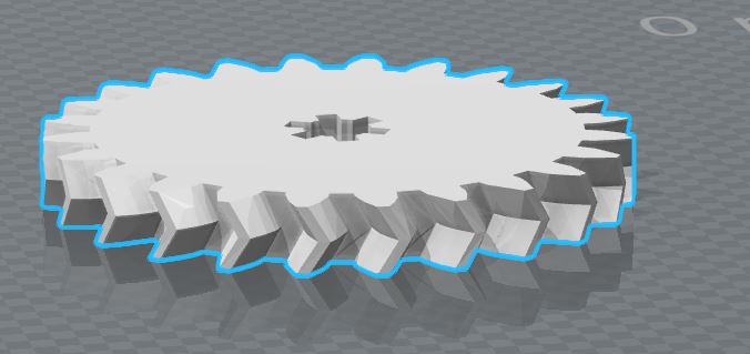
This robot uses ball bearings for each axle. Simple brass shafts could do probably the same but didn’t work in my first trials well enough so I changed to the ball bearings. I the first trials I had also standard shaped cogwheels. But as such a setup needs to have a fixation in the bearings I changed to herringbone gears. They fix each other in the longitudinal direction which use less space and reduces the friction.
It is very helpful for a robot to have encoders in order to determine how much turns the wheel did. This is often done with optical sensors but require also pretty much space. In order to avoid this magnetic sensor, a hall element is used for this robot. Most hall elements are like switch, on when they are in a strong enough magnet field, off when there is no field (or a field with the wrong polarity). A basic setup works when a wheel hosts a magnet and turns in front of a hall element. In the case of this robot only the big wheel attached to the motor allows to build such an arrangement. But due the transition this wheel also turns slowest. Therefore an as much as possible magnet needs to be placed into the wheel to get a good resolution. The printed wheels have a diameter of 3cm and the motor turns once for three turns of them. Having only one magnet leads to one impulse per 28.27cm distance the robot makes - which isn’t that exiting. So I did trials with cylindrical magnets with 1, 2 and 3mm in diameter. With the 3mm magnets a maximum of 6 magnets is possible while more than 12 magnets could be placed with the 1mm diameter magnets. But I made the experience that the 1mm magnets are to weak to grant a reliable impulse, even when 2 or 3 were placed in the same hole (“in series”). So I used finally the 2mm magnets and was able to place 10 magnets per wheel (a higher number of magnets prevent the hall element to detect each of them).
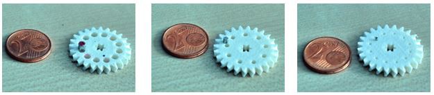
Even those magnets are really tiny, they easily can be fixed in the wheel. The holes are slight faceted are a little bit smaller than the magnets. Simply place them on a pre-magnetized screw drive an press them gently into the foreseen hole. To pre-magnetize the screw driver helps to place them with the same polarity into the wheel (keep in mind: the hall element is polarity sensitive).
Discussions
Become a Hackaday.io Member
Create an account to leave a comment. Already have an account? Log In.