 Jeremy Gilbert
After some initial success with the dot matrix display, I next took a closer look at the front panel. I was curious what it would take to decode what each of those wires did. Were each of them tied to a button? Or was there a row/column scanning type architecture?
Already a plan was forming in my mind. Now that I could drive the display, it suddenly seemed possible to restore the device to look and act like it did when it was installed on a 747-200. I could stick a 2017-era MCU inside and simulate the sort of interface that the device used to have.
I started to disassemble the keyboard panel:
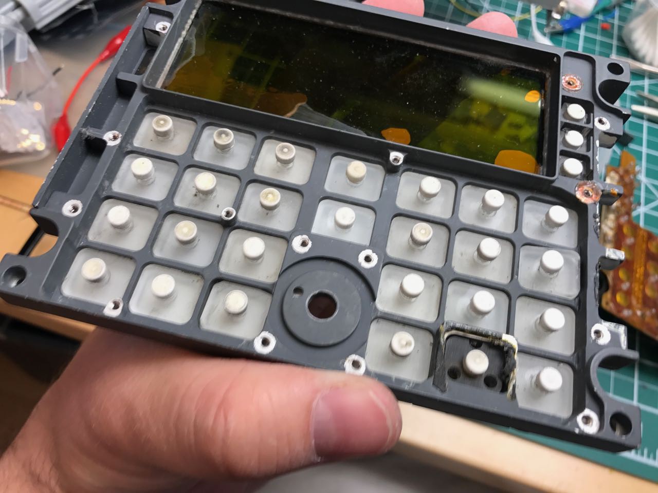
And rapidly saw that each key was not a microswitch but one of those dome contact switches that are mounted to the surface of the PCB. The wiring looks like the mask was hand-drawn - its basically a flex PCB with 3 layers.
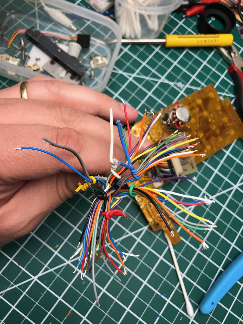
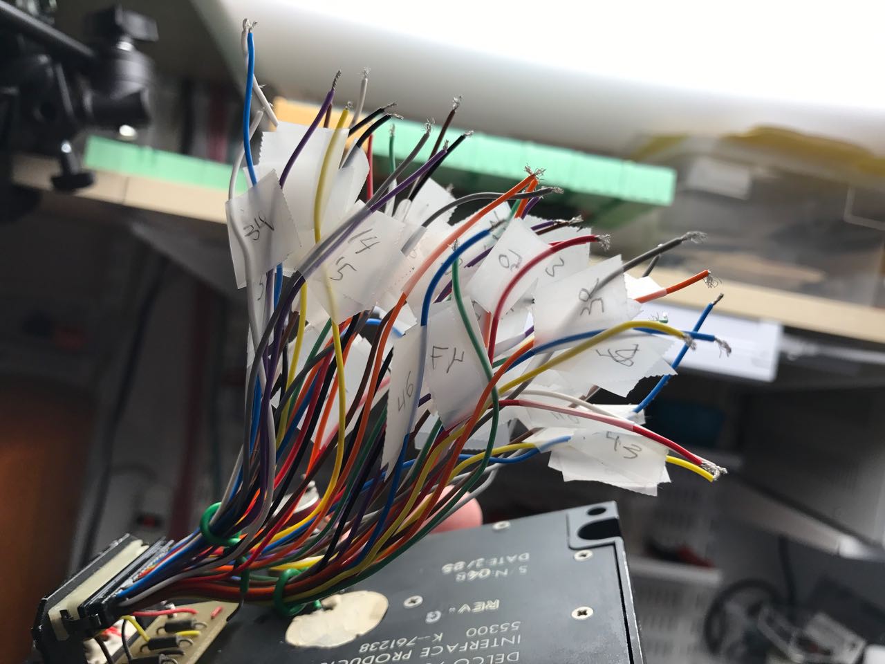
Was there any rhyme or reason to the layout or the pin assignments? I stared the painful process of finding out. First, I stripped down the wires.
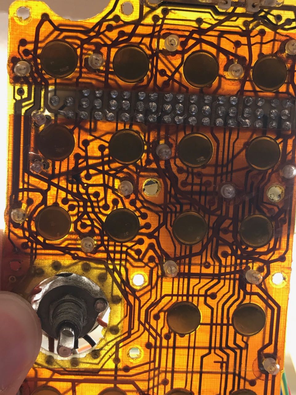
Next I began a painful 3 hour journey with a continuity tester. The primary challenge was mapping between the trace on the PCB, the net back to the wiring harness. In most cases this was obscured and impossible to follow visually. However, after removing some of the kapton tape (they HAD kapton tape in 1979??) I managed to start figuring out where things connected on the PCB. Next was the mapping between the wiring harness and the actual wire. The actual connections were obscured by a gigantic blob of (probably toxic) sealant.
Each tracing step required mapping from the element on the PCB to the breakout, and then from the breakout to the wire.
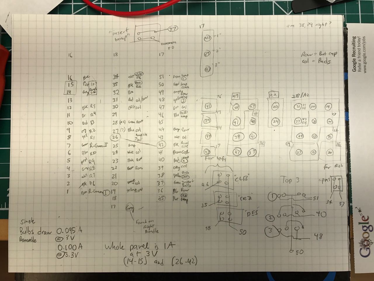
Finally, i ended up with a pin chart like this one, now preserved for posterity:
Along the way, I labeled each wire.
I can't guess how long that I spent on this but it was several evenings over the course of a week before it was done.
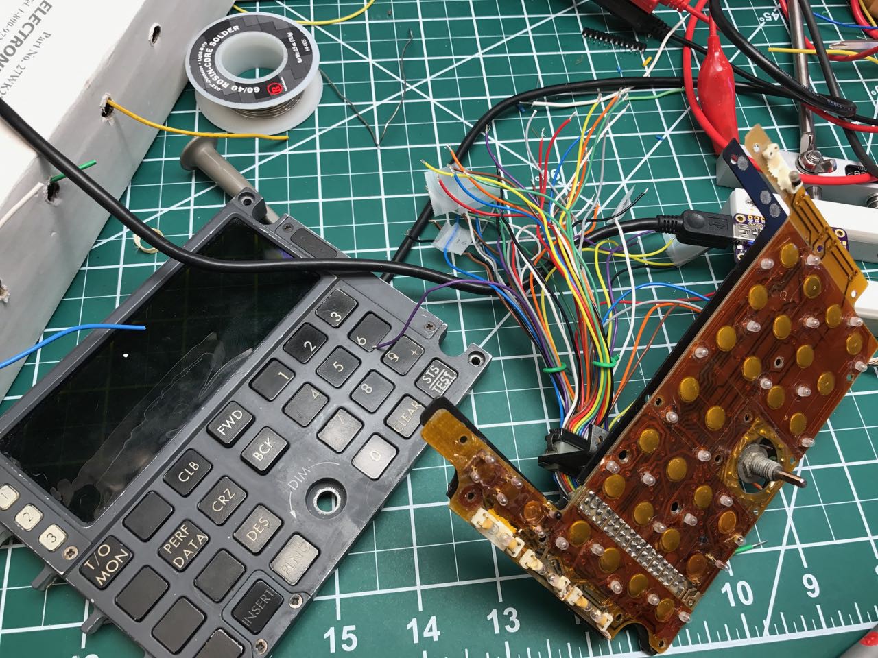
I also did some tests to make sure I understood the various lights on the board:
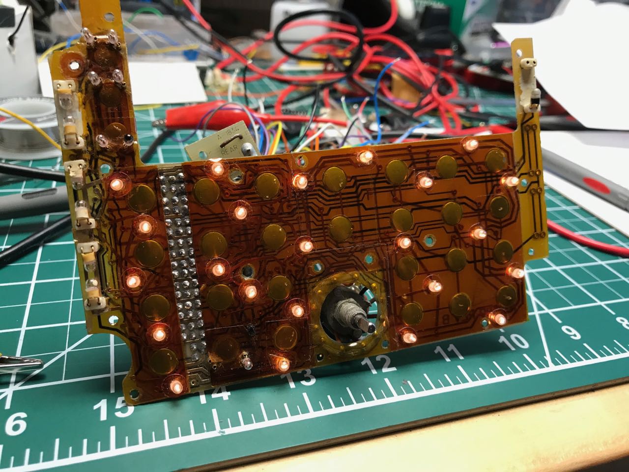
All of the lights you see on this board are basically grain-of-wheat ~3V incandescent bulbs. They are probably impossible to replace once they burn out now. Who makes 5mm incandescent bulbs anymore? [sadness] I'm hoping that if i drive these bulbs at under 3V i can get them to last a lot longer. The bulbs actually providing backlight illumination to the keyboard are surprisingly soldered directly to the PCB, and its unclear how you'd easily replace them given the copies amount of glue and kapton tape involved
Discussions
Become a Hackaday.io Member
Create an account to leave a comment. Already have an account? Log In.
3V wire terminal lamp from Mouser, 60mA, 100,000 hour life. 384 in stock. http://www.mouser.com/ProductDetail/JKL-Components/7207/
Are you sure? yes | no