 Jeremy Gilbert
Earlier in the build, I demonstrated for myself that I could light up ONE of the little QDSP-2273 4 digit displays by connecting it to an arduino with some jumper wire.
Now my challenge was to make 24 of the display modules work at once. Theoretically, this should be simple. The display assembly I extracted from the box was already wired for all 24 to be daisy chained together. But I quickly realized that plugging the whole thing into an Arduino would be disastrous. Each column of the display has to be driven from my microcontroller, and the current requirement was easily 1 amp or more at 5 volts. This is quite of bit of power.
Normally, when I have power challenges like this, I turn to a MOSFET. For instance, this one from adafruit:
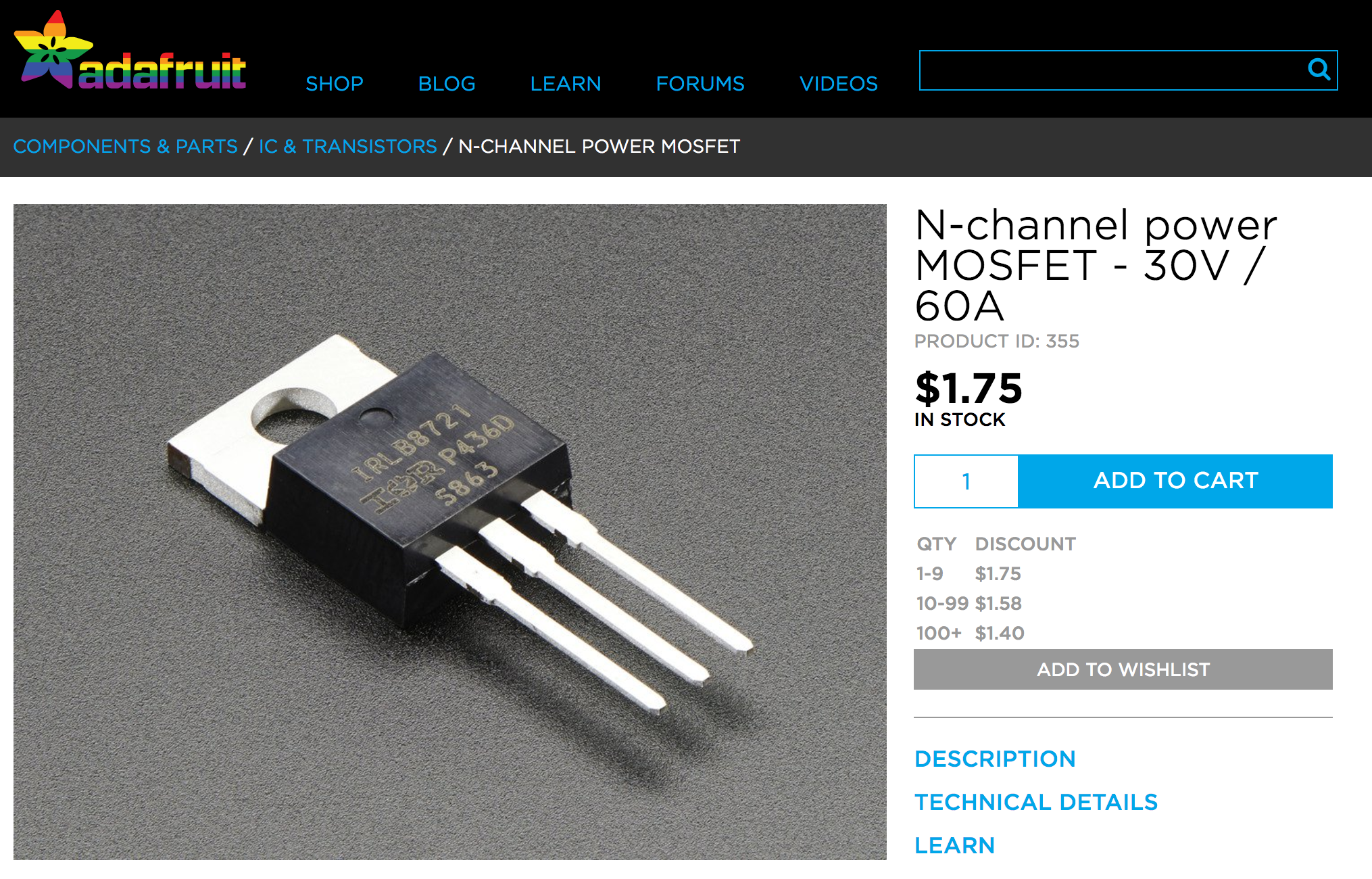
This device will let a microcontroller switch 30V at 60 amps, easily enough for this application. If I used 5 of these devices, I could switch each of the 5 columns of the display. Sadly, I did not have enough of these little guys laying around my workshop.
After some thought, I realized something important. The CDU/PMS unit itself probably had the same problem that I have. Its 1979-era logic gates probably couldn't drive that much current either. Somewhere inside the box ought to be some form of current switch.
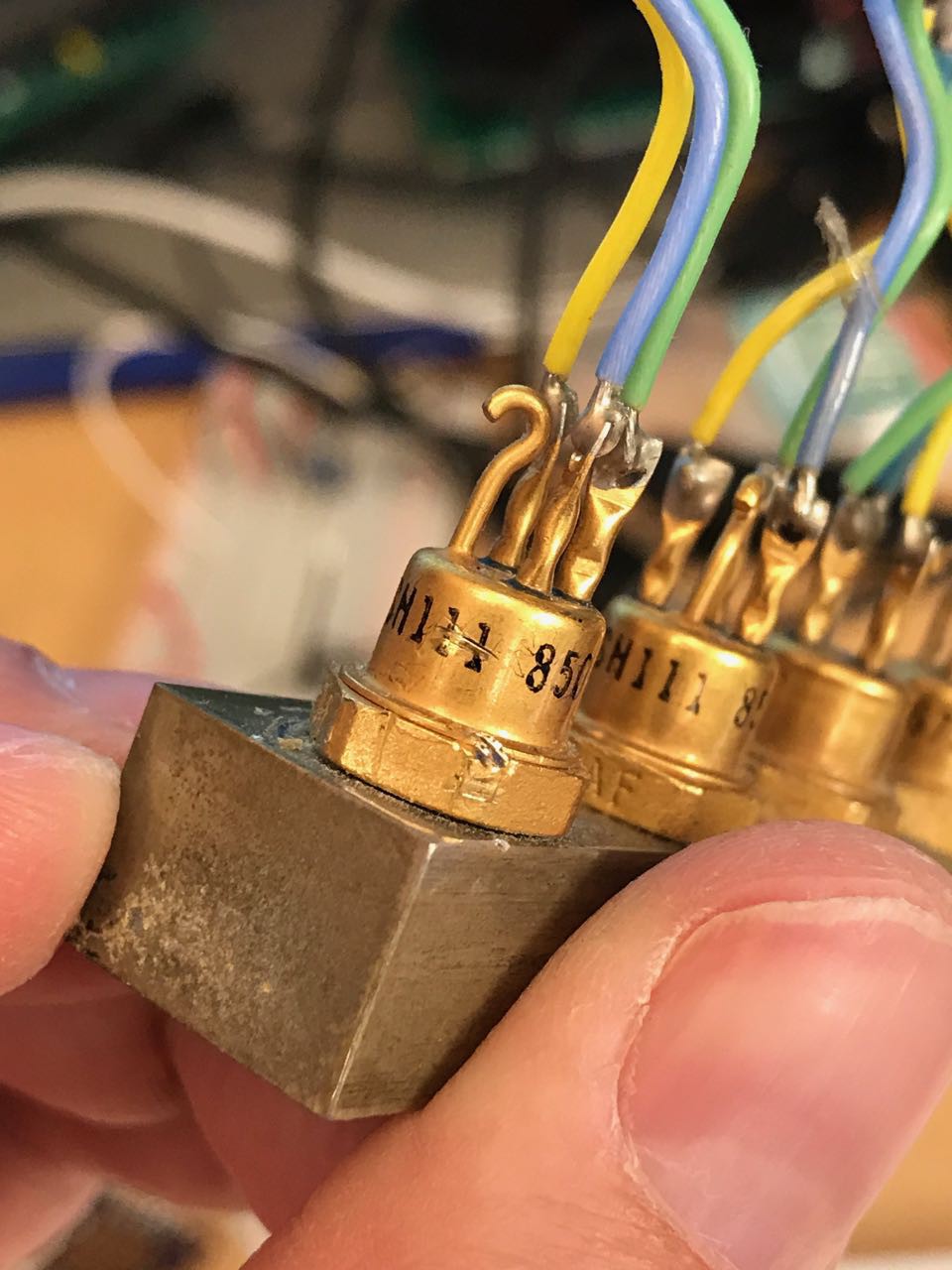
Sure enough, I found a bank of 5 transistors with a heat sink on one of the PCBs:
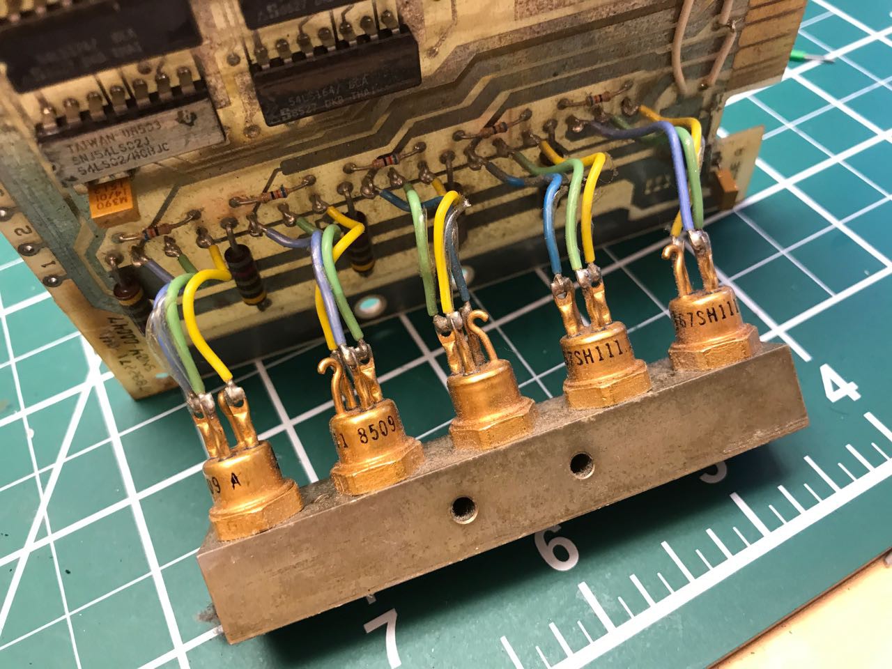
Look how cool they are! They even have their own solid metal heat sink and exposed leads.
Now a bit of cleanup and a part search..
I was unable to locate part number "S 67SH111 8509 A" so it would be important to prototype this first. Some quick probing with a diode meter, and I confirmed they were PNP transistors.
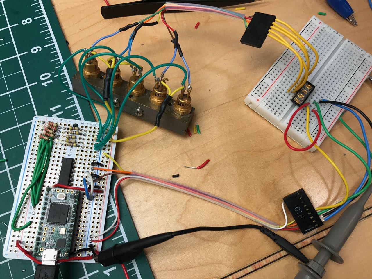
Below you can see my proof of concept. In this proof of concept, one of the columns is being driven through the transistor:
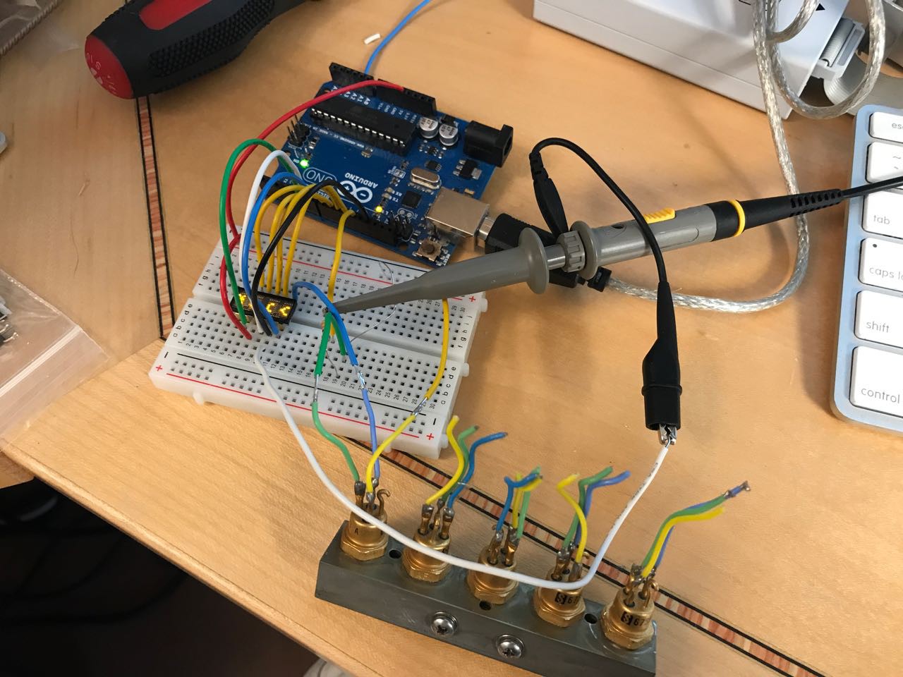
And here is the schematic:
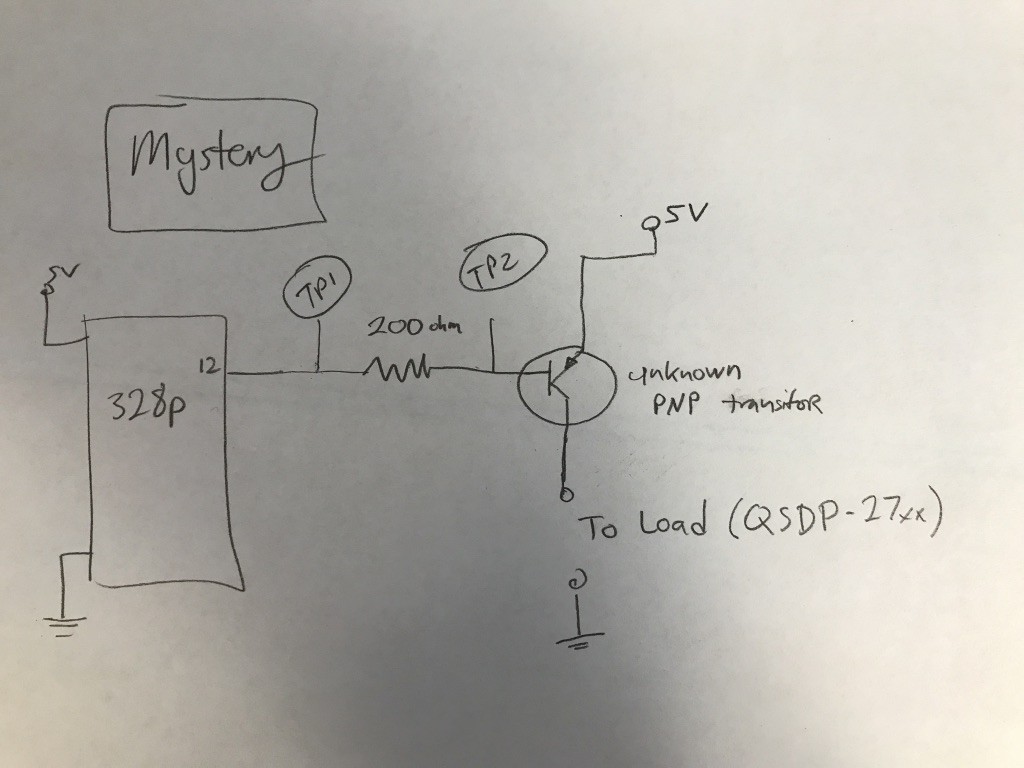
Along the way I encountered a mystery beyond my current EE knowledge. Based on my primitive understanding of analog electronics, a transistor is basically a current-parallel switch. The current you feed into the base is magnified and becomes the current that passed through the transistor from the high-energy device. When you want the switch to be active, you lower the voltage flowing through a resistor and feed that into the "base" of the transistor.
When I measured the voltage from the microcontroler, I see what I expect, which is a signal oscilating between 5 volts and 0 volts.
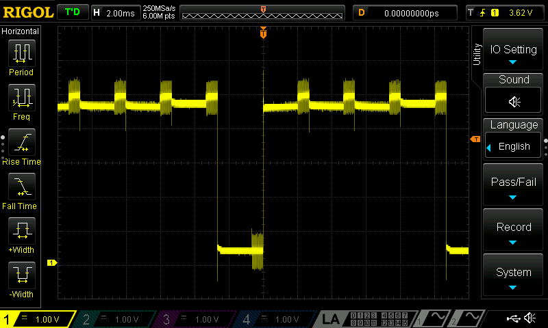
But when I measure from the base of the resistor, you can see the voltage doesn't actually drop to zero.
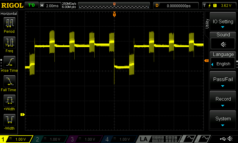
Is that just because the resistor is causing a voltage drop? If thats so, why does the transistor actually work at all? It barely seems to fall in voltage more than an volt!
Maybe in my next life I'll go back and take analog electronics in college.
In any case, the design seemed to work, so I decided to move on in the profound hope that what I don't know won't come back to hurt me. The next step was wiring up all 5 transistors and running a proof of concept test.
 For my full proof of concept, I decided to switch from using an Arduino to a Teensy 3.1. The Teensy is a 96Mhrz MCU board made by PJRC. It has far more RAM and speed than an Arduino and has been one of my goto components for my projects because of its excellent library and technical support.
The only challenge was that while the Teensy is OK with receiving 5V, it doesn't actually drive anything higher than 3.3V from its pins. This is a problem - to turn my transistors off, I need to bring them to a full 5V.
After some vacillation around my design choices, I settled on use of a pull up resistor. To turn ON the display column switch, I drive the pin to its LOW state (0 volts.) To turn OFF the display column switch I switch the pin from an OUTPUT to an INPUT, which places the pin at a high impedance state and allows the pull-up resistor to bring the transistors's base to 5V.
Code to pull the pin low:
pinMode(column_pin[c], OUTPUT);
digitalWriteFast(column_pin[c], LOW);
delay(2);
pinMode(column_pin[c], INPUT);
I'm frankly not sure if this is a recommended practice (remember what I said about my level of EE training.) But it worked. Hopefully someone can help fill in my knowledge gap here.
After some successful proof of concept tests, I decided to try writing text to the display. To do this, I needed to build a character generator that would take a string of ASCII and give me the dots to write out each character. In turn, I needed a 5x7 font to feed into the character generator.
As luck would have it, I discovered the work to create a 5x7 font had already been done by none other than LadyAda herself. After deciphering the font format, I managed to get the following proof of concept with some arbitrary text:
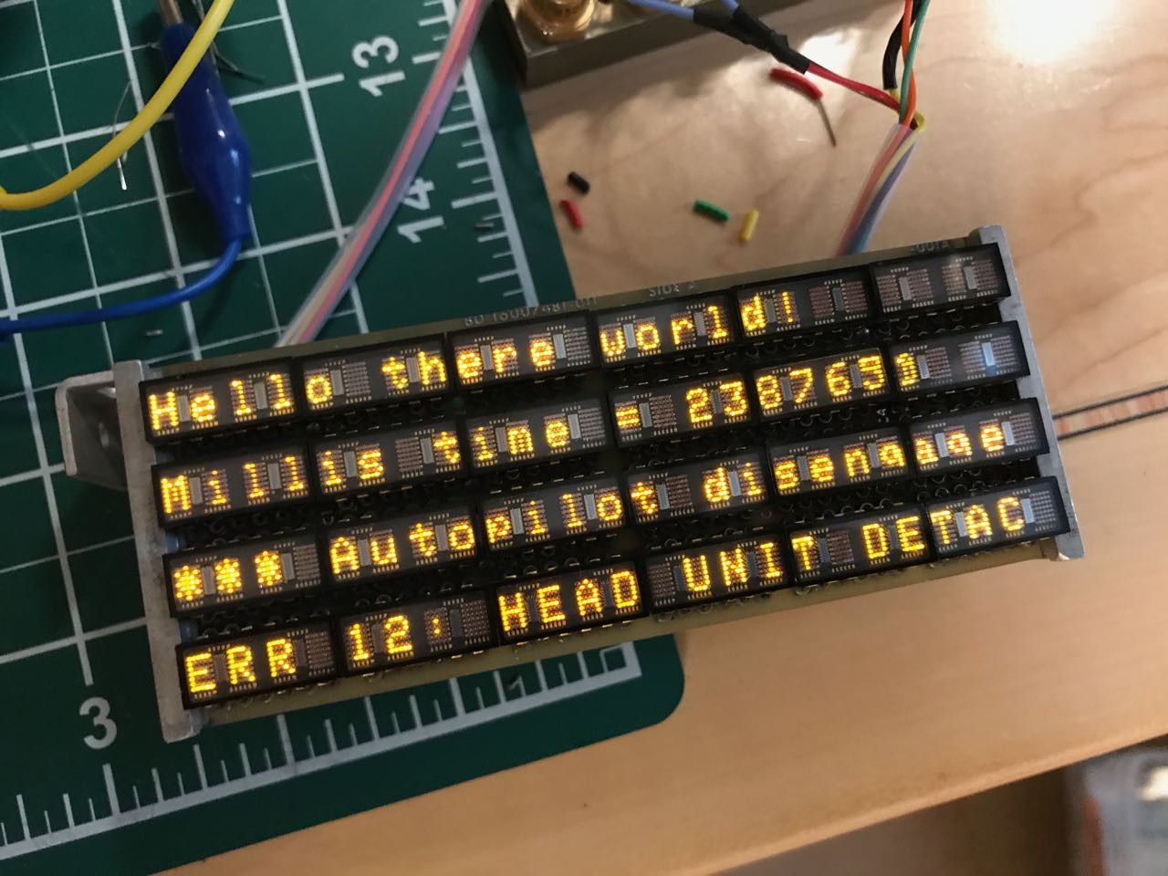
Success!!!
When all of these little display elements are on, the display generates a ton of heat. No wonder they are packed into a heat-sink!
Discussions
Become a Hackaday.io Member
Create an account to leave a comment. Already have an account? Log In.
I think that the 67S111 is an old Solitron part.
Are you sure? yes | no
such a lovely display :3
Are you sure? yes | no
Regarding the voltage on the transistor: You want to measure the base-emitter voltage, not the voltage between base and ground. For an NPN transistor, the emitter is often connected to ground, so the two voltages are the same. But not for a PNP. Keep in mind that the transistor will turn on once its base-emitter voltage exceeds around 0.5-0.7 volts.
Are you sure? yes | no
The oscillograms show a BE voltage drop of around 1,4V which would fit perfectly for a darlington configuration of 2 transistors. And that is absolutely reasonable as power transistors of the aera, especially PNP, had a lousy current gain. Perhaps only 10 or 20, so for 2 amps of output current you would need 100mA or more of base current. Nothing a logic chip will provide. So you cascade 2 transistors to multiply their current gain. - and double their base emitter voltage drop.
The use of a pull up resistor together with 5V tolerant IOs is absolutely acceptable.
Are you sure? yes | no