 Jeremy Gilbert
A week later, a giant box arrived at my doorstep from [aircraftstock]. I've ordered a few times from this seller and always been quite happy. He packs everything in dense bubble wrap. He also includes the inventory and removal tags on the device.
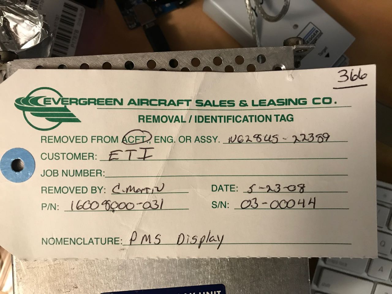
These tags are important because aviation equipment is FAA validated and I think in some cases you have to be able to demonstrate you know the provenance of used parts that you later install in a new airfraft.
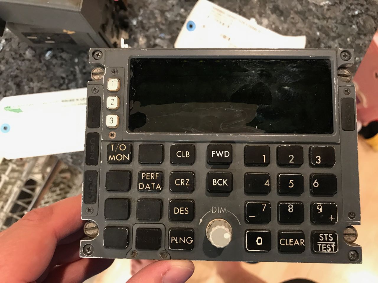
Wow, what a georgeous front:
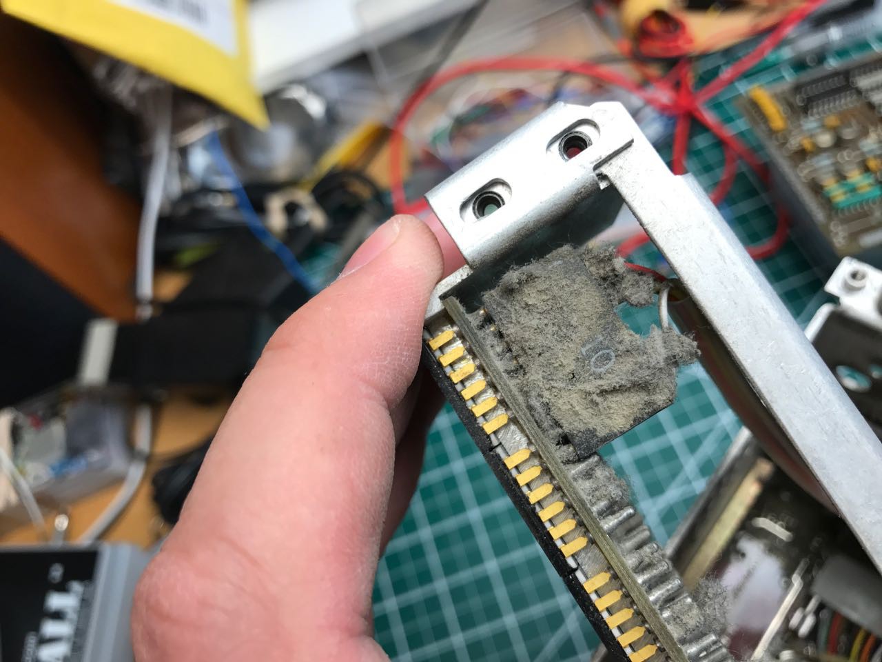
Next I started with opening the case. A decade's worth of grime and aviation dust was apparent everywhere.
My first step was to remove the front panel
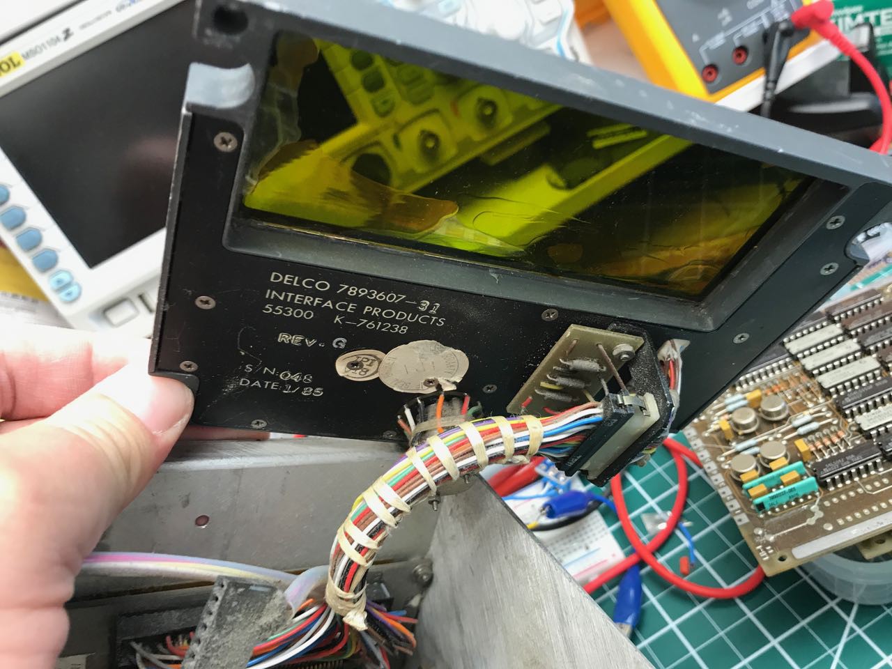
As you can see, it was tied to the rest of display with a 51 pin custom cable. Note how the wiring harness was hand-tied.
The display was especially mysterious. I had been expecting a VFD display. Instead there was this curious assembly made up of individual chips. I immediately thought of these retro dot matrix IC chips that I've seen on Digikey.
Behind the front panel and display are a row of removable circut boards. These boards contain all of the logic to drive the display and decode the keyboard and presumabley translate it into some private protocol that can run between the head-end unit and the avionics device.
Here is a closeup of one of those boards. Have a look at the transistors and their massive heat-sink. This becomes important later.
The display subassembly was incredibly dirty. The first thing I noticed was that on close inspection it actually acts as a heat-sink. Look at how the chips sit up against a custom peice of machined metal.
On the rear view, you can see how thick the traces were. I originally figured these must be power and ground, but actually I was wrong as you'll later see.
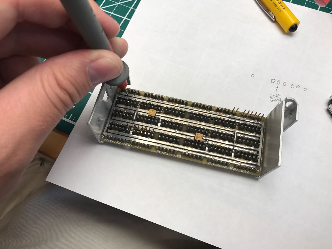
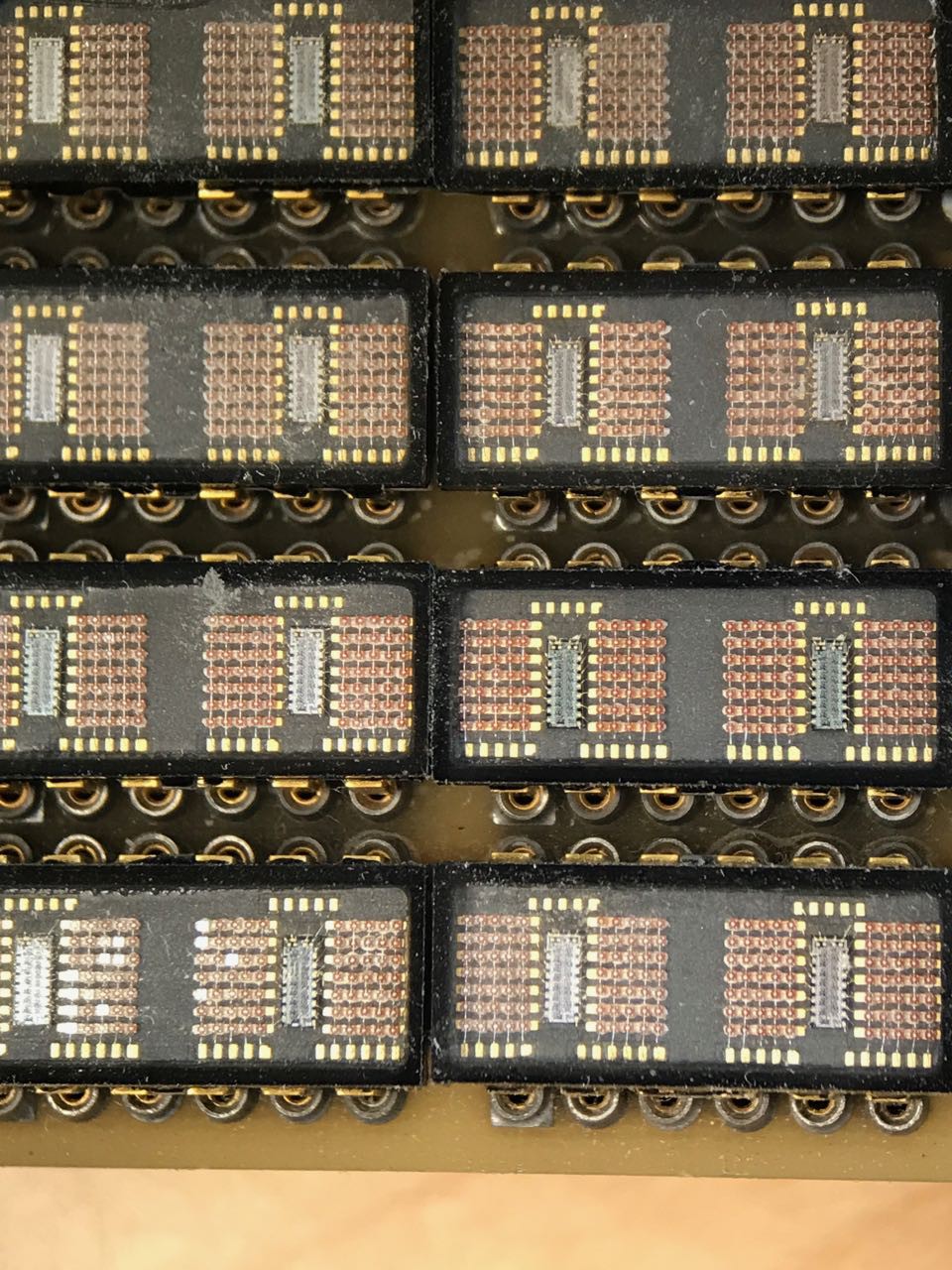
On close inspection each of the display chips contains two dies
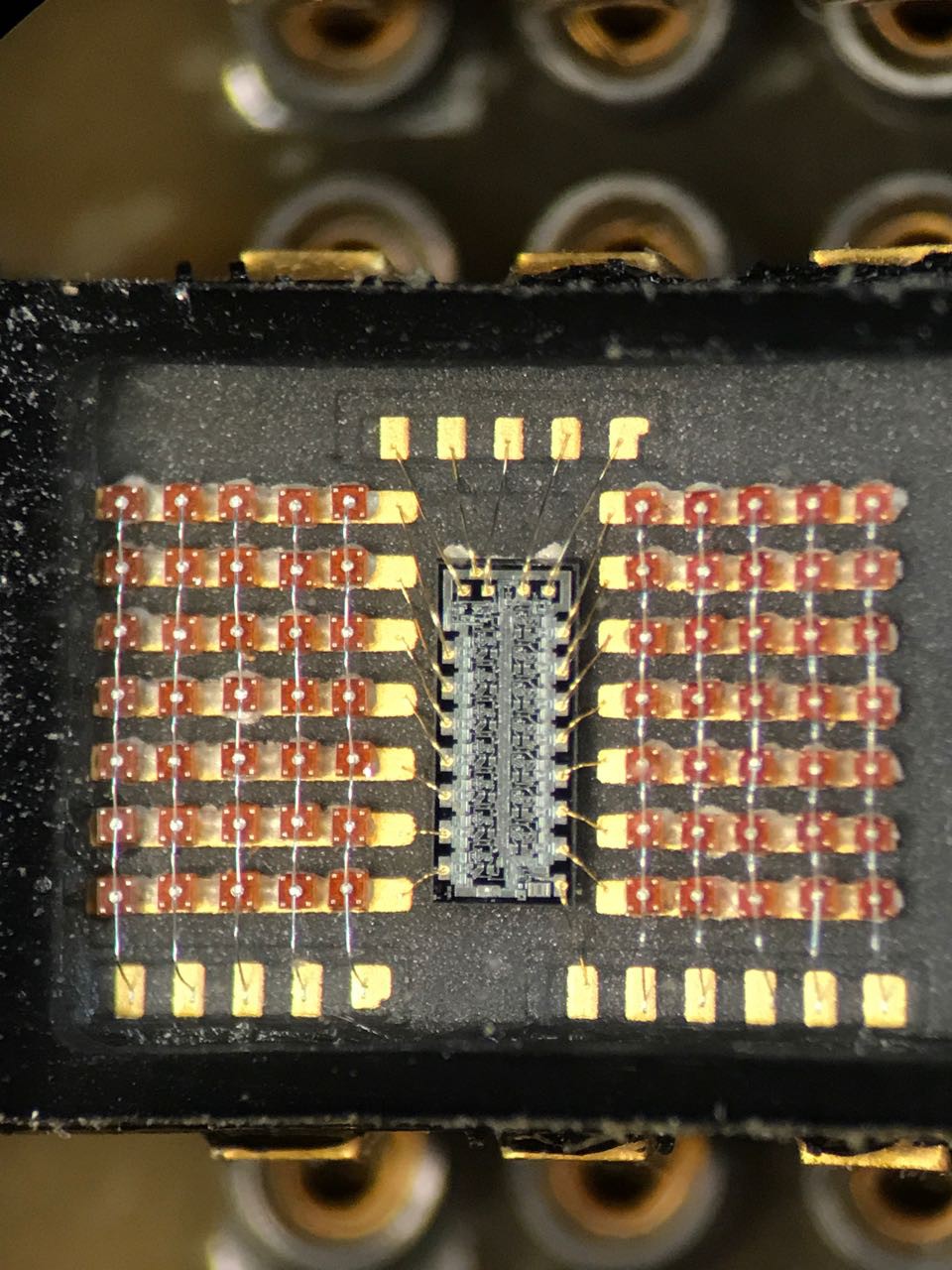
Time to put it under a microscope and actually look at it.
I can't explain why, but the whole thing looks remarkably hand-wired. Maybe someone can explain why.
 I started mapping out the pins and traces. Again, I was assuming that the pattern was feeing power and ground to each chip and that was the reason for the wide traces.
Next came a ton of sleuthing around. The chips were labeled as QDSP-2273. That part number doesn't appear anywhere on Google. But I did find this nice explanatory link for the type of technology used:
[Hewlett-Packard HDSP-2xxx Series - The Vintage Technology Association]
Hewlett-Packard first introduced the in 1976, as the display elements used in the HP 9825A desktop computer/calculator. Unlike HP's earlier multi-character displays which require external multiplexing circuitry, the HDSP-2000 is driven by four internal SIPO (Serial-In-Parallel-Out) shift registers, grouped in pairs in two planar dies housed within the display package. Serial data is shifted into the display in 28-bit words, and converted to parallel data which directs the multiplexing of the LED elements. All HDSP-2xxx series devices are packaged in glass and ceramic, and some models are actually built with red glass, a unique feature among the pantheon of early LED displays.
After some difficult pain with guessing search terms, I managed to locate an old PDF scan of the data sheet for the HDSP-2xxx series. The architecture is unusual. Its arranged where each ROW is a constant current sink driver that is connected to a shift register. Each column anode is actually driven externally. The idea is that you turn on one column and then serially clock out the row values. Then you turn on the next column and clock out the next chain of row values. Rinse and repeat.
Eventually I found that someone named [J Silva] had already managed to write an Arduino code example to drive one:
[Coffee, bits and bikes: HDSP-2000LP Arduino](http://bitsnbikes.blogspot.com/2010/05/hdsp-2000lp-arduino.html)
I spent another half hour carefully examining the traces of the PCB to see if this chip actually was wired the same way as HDSP-2000. I didn't want to make any assumptions. I was fully aware that I had only one shot to get this right, and it was unlikely there was a ton of ESD protection or polarity protection on the circuit. In other words, one wrong move and I've fried a chip I could never easily replace.
Eventually I convinced myself that the PCB actually was wired as though each were a HDSP-2xxx. It turns out the PCB is multi-layered and contains routing so that each chip gets their own access to 5 anode column drivers. Check one complete!
Next challenge was voltage. Airplanes use wacky voltage. In the past I've seen devices that expected everything +/- 48V AC to -5/+12 volts DC and everything in between. In the total lack of more information, I decided that this was probably TTL logic based on the era and that 5V was probably safe.
With the excited rush of a kid opening a christmas present, I giddily removed one of the chips and wired it up. I held my breath and applied power.
It worked perfectly! Thank you [J Silva].
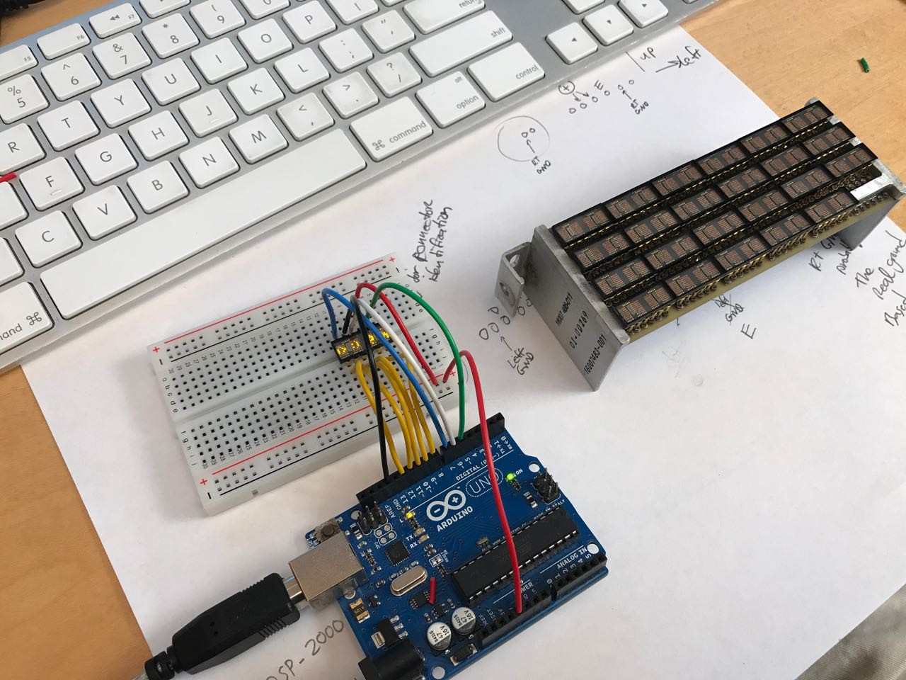
Still giddy, I took photos and shared on twitter. I now knew I could potentially drive the entire display myself!
This demonstration, while exciting, raised some serious problems. For one, the current requirement was extreme. The single 4 character display was quite warm. I don't recall exactly, but I think i measured around 100mA just running the simple demonstration provided by [J Silva].
Discussions
Become a Hackaday.io Member
Create an account to leave a comment. Already have an account? Log In.