 Sophi Kravitz
I presented on this project at Hackaday Belgrade (I'm at 1:44:32) and had it working just enough to talk about :)
I still have a couple of issues to work out, and one of them turned out to be a huge bummer.
- Two of the motors (both on same driver #1) spun at slower rpms than the one (on second driver #2).
- I looked at the driver chip under the microscope and noticed that I'd soldered it slightly off the pad so that the junction provided half a trace-width (6 mil not 12 mil). Side note: I cannot find where the trace units are in Eagle. I assume since my board is in inches, the traces are too...
- Fixed this by removing and re-soldering the chip
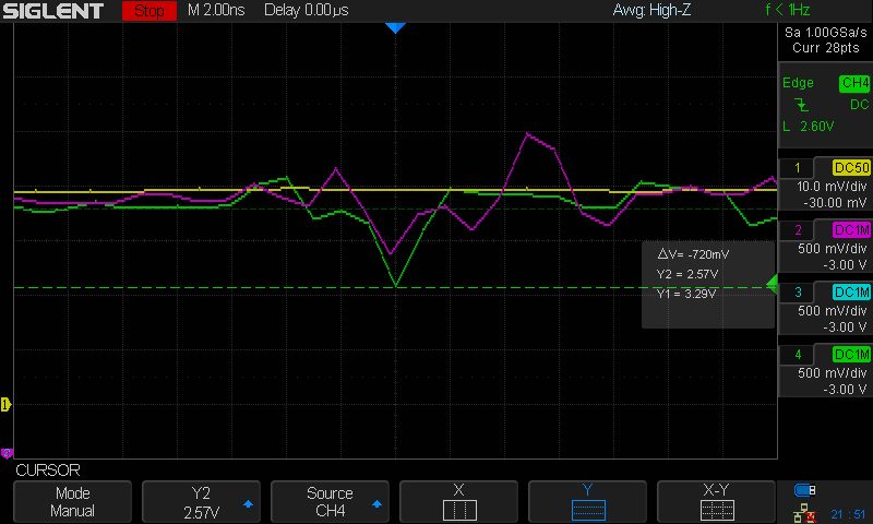
- Now that all the motors draw the same current (about 350mA max each at 3.8V - 4.0V), new power problems arose. I noticed that the ESP kept resetting which indicated that the voltage was dropping below 3.0V for some short length of time (5us).
Last night I worked with Ed Nisley, a great friend and an engineer with better tools than I, to discover what exactly was going on. Ed has a Tectronic device from the 70s which coupled with a hall effect sensor converts the signal to a current value to be viewed on a scope. We looked at the current (in yellow), which fortunately doesn't dip under load. However, at the point of reset, with all three motors running (one shown here in purple) + the ESP8226 reaching out to WiFi (1.2A) we observed a voltage dip down to 2.6V at the ESP8266 supply/ buck-boost output (green).
This could be because the back emf is going back into the voltage supply due to such long traces on the board. A little hard to see, but the highlighted trace is the battery supply trace.
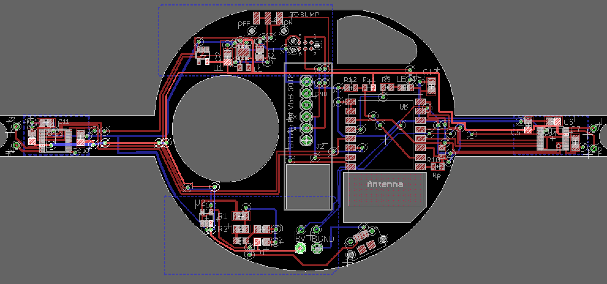
I'll recreate some of this test and post scope pictures later. My plan to troubleshoot is to solder three fat wire paths over the board: a path directly from battery supply to buck boost converter + battery supply to each driver.
For now, this is a pretty big bummer as if this is the case, I'll need to redo my layout to put the buck-boost (top left) converter much closer to the supply (bottom middle).
Stay tuned...
Discussions
Become a Hackaday.io Member
Create an account to leave a comment. Already have an account? Log In.
It's not just about the power trace. Yes, it's thin and needs to be wider, but in these kind of applications when you're mixing high power dirty stuff with sensitive digital ICs, you also need a solid ground plane ( not ground trace !). I suggest you should move on to a 4layer PCB. If it's not possible, design a good solid ground, and fill up empty space on the board with ground. Also, you should avoid placing the ESP in the path of those high currents. One way is to have a star-ground design. A careful placement of power-decoupling capacitors as close as possible to ESP power pin(s) is also mandatory. I think you have to redesign this PCB. I doubt strengthening the power-trace will solve the issue, but fingers crossed :)
Are you sure? yes | no
Bodge on some big through-hole caps directly to the ESP's power pins?
Are you sure? yes | no
maybe. I have 1.2 grams extra to work with :)
It could also be that the ESP isn't a great choice for small brushed dirty motors. I've had so many struggles keeping its power supply steady.
Are you sure? yes | no