The first thing that needed to be done, was soldering the new connector to the old wire, to be able to fit everything in the laptop again. It all looked like 4 twisted pairs (white/blue), some GND wires and some V+ wires (Vss? Vdd? Vcc? I never know what they mean without the context). At least, that's on the end of my new shiny adapter PCB. On the TFT it seemed to have one additional twisted pair, but instead of something looking like GND and V+ a lot of rainbow coloured wires. At least this was consistent with the inverter colouring (red - orange - yellow - green - blue - purple, meaning: 2x GND, 2x V+ and an enable & PWM signal somewhere - I'll write up on that later). The twisting didn't match for all, some ground wires seemed signal wires and one of the V+ wires (red colour) seemed GND. Ah well.
TL; DR: many wires. Colouring strange. Just cut & solder 1-by-1. Result:
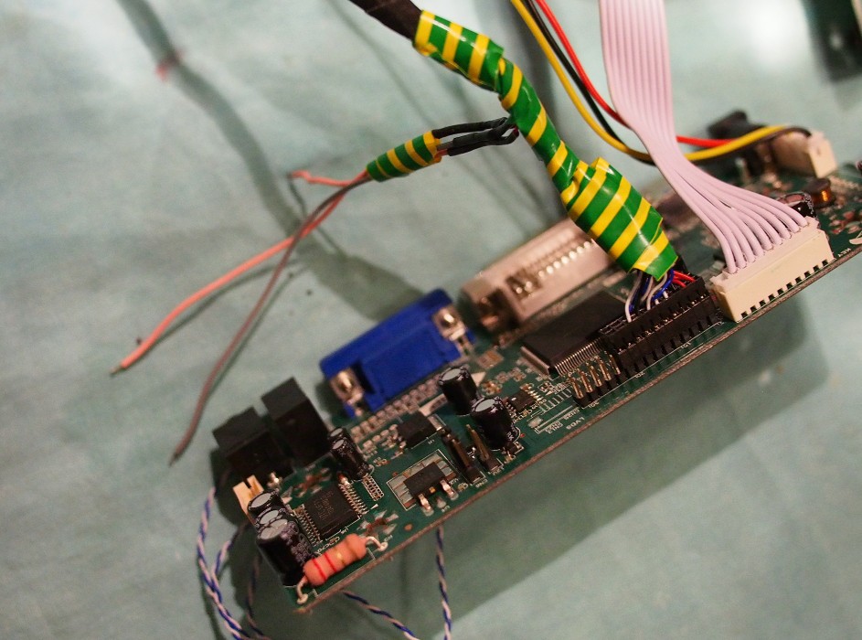
Sorry, I already had the tape on... Anyway, it worked the first time - a miracle. BTW, the grey - pink - pink wires are GND, V+ and PWM for the inverter, on which I'll write later.
Then the wiring from the USB2DVI to this PCB. Trusty pinouts.ru to the rescue. I discovered that DVI has 2 links, of which apparently one is needed up to Full HD-ish @60Hz. That last info was from wikipedia, which also had clear information on what data channels are for link 1 and for link 2. I should have looked at the nice picture:
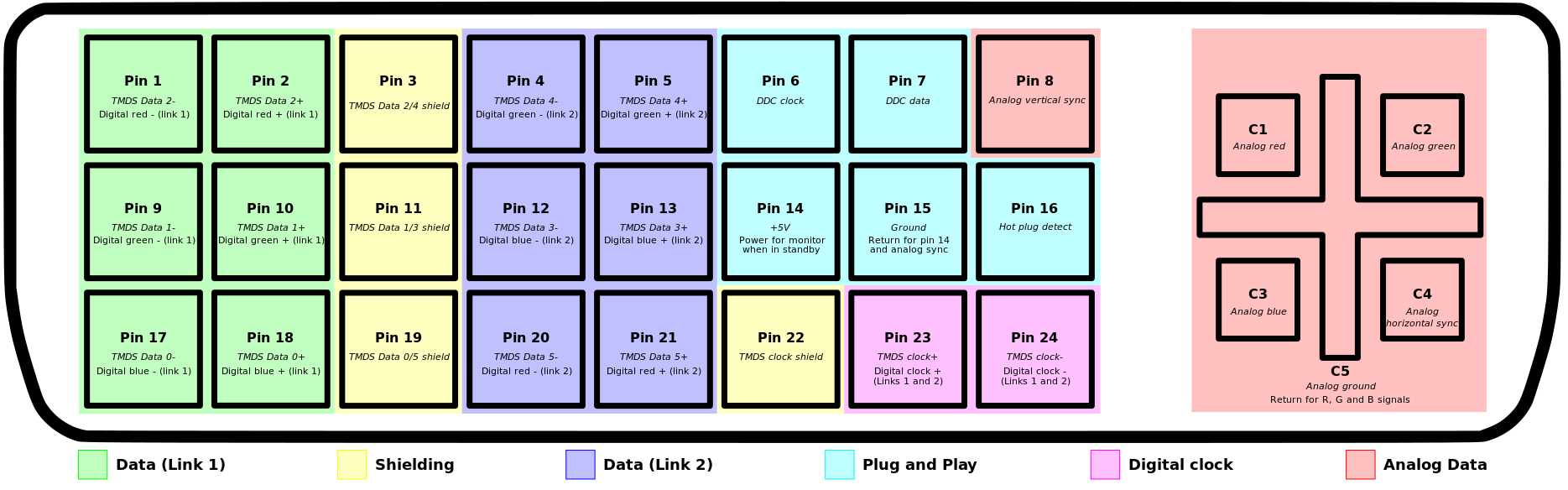
By Ionuion at English Wikipedia, CC BY-SA 3.0, https://commons.wikimedia.org/w/index.php?curid=4379981
...because looking now at the picture it all really looks logical.
I did not. I counted the pins, tried to figure out how everything was mirrored from screen to connector to under side of PCB, wired everything up, accidentally mixed up the red channel of link 1 and link 2, corrected it, connected everyting and... it didn't work. I pulled off all the wires, 13 in all, only to find afterwards that the DisplayLink Presenter software seems to only work again after a fresh reboot, not giving a screen on the second USB connect. I almost thought the USB2DVI was dead. Connecting it to my PC gives a kernel panic.
A few days later I tried again, and it all works well. After thinking for a while "if only I would have bought a VGA adapter" I thought of the analog part of DVI. Looked up this nice wiring scheme from pinouts.ru again, and only about 20 minutes later I had this:
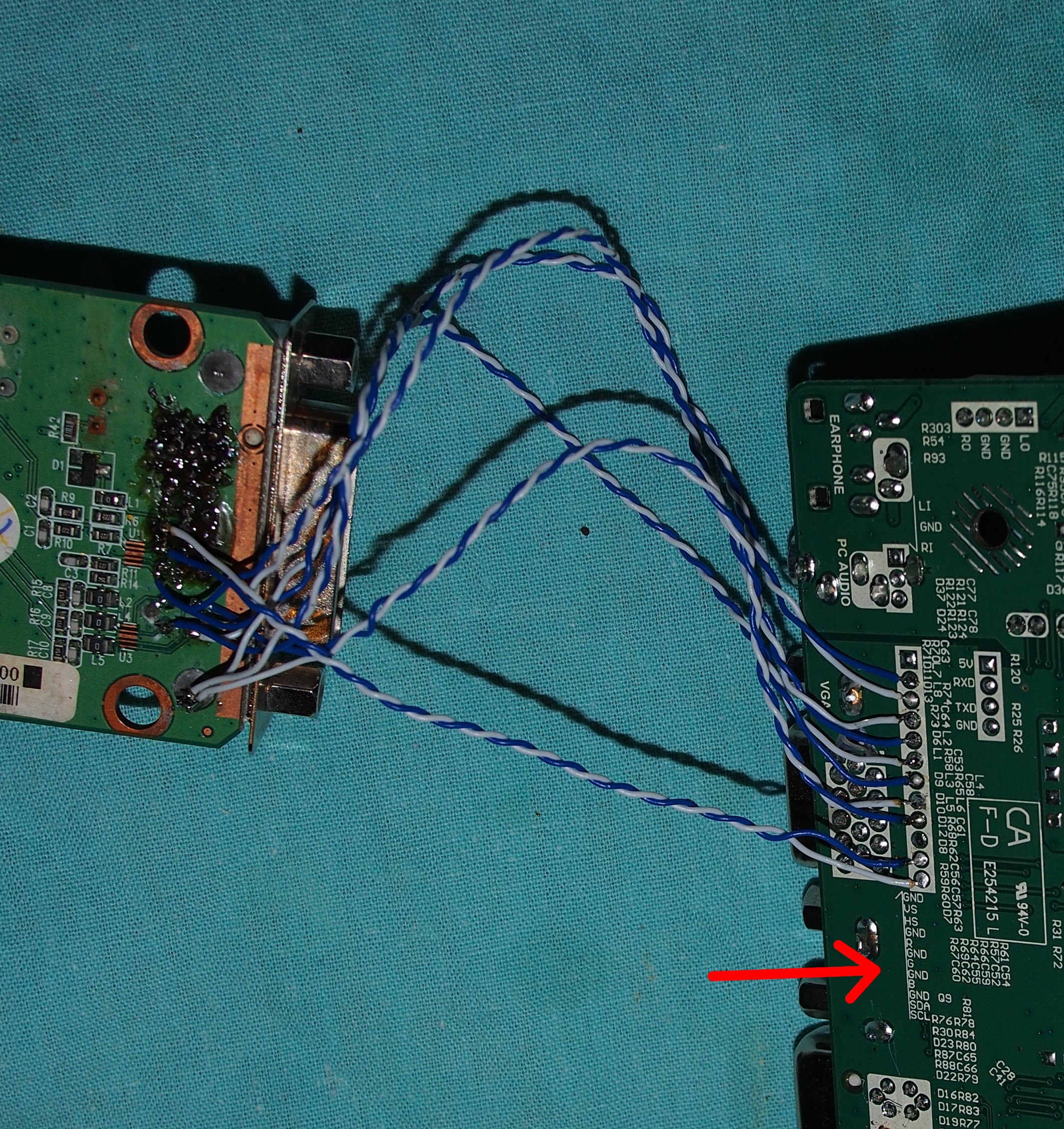
There even was a conveniently very simple VGA connection strip, completely with printed naming, on the PCB. Only 8 wires needed. Because I had some twisted pairs left (from the old LVDS wire) I did the colour signals with their own GND paired.
And it works at once!
Still thinking if I will keep it this way, or rewire. Because this way I might need to correct overscan etc. At least I have the GND and I2C monitor ID wires already wired up correctly for VGA or DVI alike...
Discussions
Become a Hackaday.io Member
Create an account to leave a comment. Already have an account? Log In.