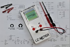
Revision 2 resources are available from the download link as a TGZ file. More details and documentation will be posted after fixing a few issues with the current revision. Prototype boards shown in the image were ordered from OSHPark (1.11 x 1.56 inches, $8.65 per three), and all other components are available from DigiKey (Gerber files and full BOM available in the aforementioned TGZ file). Firmware is the same as that available for download from Adafruit, with minor adjustments to the Makefile to be compatible with my programmer. Possible future improvements include a 3D-printed enclosure (it is easy to create a short between the batteries), and a rechargeable LiPo battery.
0%
0%
Mini TV-B-Gone
Remix of the TV-B-Gone sold by Adafruit, originally made by Mitch Altman
Become a Hackaday.io member
Already have an account? Log in.
Just one more thing
To make the experience fit your profile, pick a username and tell us what interests you.
Pick an awesome username
hackaday.io/
Your profile's URL: hackaday.io/username. Max 25 alphanumeric characters.
Pick a few interests
Projects that share your interests
People that share your interests
 core weaver
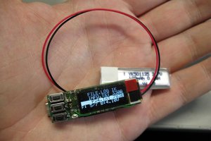
 jaromir.sukuba
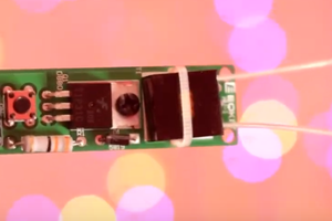
 fr.shirvan
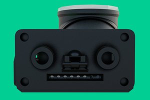
 Lex Kravitz