• Knowledge is (kg*m^2)/s^2

    Machinehum (Ryan Walker)08/11/2017 at 02:36 0 comments

    It's about time SoundHive got a convenient way to power itself. The bench power supply works fine, but AC to DC adapters are cheap and readily available. For 25$ on Amazon you can get yourself a 24V adapter (That's ~1$/volt!) For an interface a DC barrel jack should do the trick. 

    That's fine and dandy if you're at home, but what if you're on the go? That's where cheap hobby li-po cells come in, in the spirit of modularity, I'll just hang an XT60 connector off the side. That allows the user to pick whatever battery capacity they require. It's also possible to power Soundhive off 4-6 cells as it has such a wide input range.

    But unfortunately it's not as simple as plugging in the batteries and chugging along until they die. If you drain li-po cells flat, you run the risk of permanently damaging the cells. So you're going to need some sort of cutoff circuitry. I'm going to talk about how I did this below.

    Typically Li-po cells are ~4.2V max, ~3.6V nominal and ~3.2V cutout. That means for a 4,5,6 cell battery you want the system to cutout at 12.8V, 16V, 19.2V respectively.

    The first and most important thing the system needs is a fixed supply, for this I chose 5V. You can't just use any old regulator, it needs to be extremely low quiescent current, this is because even after the battery is cutout - this supply is still running, along with everything else it's powering. For this I chose a TI LM9036MX-5.0/NOPB - it takes about ~20uA to operate.

    The user will have to select weather they're using a 4,5 or 6 cell battery. This is done by moving a jumper to the correct position this is changing a simple voltage divider.

    After the regulator stage there's a dual opamp stage, the first is a Comparator with hysteresis. The reason for the hysteresis is as follows - when the system is drawing current, their is a voltage drop over the batteries internal resistance, although this is minimal, if a standard comparator was used the system would shutoff, then the voltage would rise to the open circuit voltage, thus turning the compactor back on and drawing load, then shut off again. This would continue for a while until the open circuit battery voltage was drained below the trigger point.

    The second opamp is an inverter.

    As with the regulator, it's important to keep the quiescent current draw of the opamp + resistors low.

    The final stage of the circuit is an N-channel fet, this connects the entire soundhive PGND to the GND of the battery. The most important characteristic of this FET is to have a a low Rds(on), this is to minimize joule heating of the part, which of course results in a lower efficiency.

    For cutoff circuity, that's about it. I'm thinking about integrating a battery charger into the next revision, that would allow a pretty awesome on the go / at home setup.

    Entire Circuit:

    Pretty Kicad 3D happyness:

    Next up is a PCB for taking input from a 3.5mm AUX jack, and feeding it up the stack, that certainly doesn't warrant a blog post After that I want to do a SW FFT board that can live on top of the entire stack. Most likely designing all the LED driver circuitry from scratch! Smells like smoke already!

  • Fire up your loud

    Machinehum (Ryan Walker)07/25/2017 at 18:53 0 comments

    Finally got around to testing the boards today. I had an old broken guitar amp lying around, after robbing the speaker from it + a couple of bodge wires it was finally time to see what this suckers made of.

    On a 12V supply (this guy can go to 24V), both gain jumpers removed (max gain) and the phone on 25% volume it was so loud that I'm confident the neighbors would be pissed if it was left on for more then 5 minuets. At 50% volume my ears hurt and speaker started vibrating on the desk as they're not secured.

    Really stoked on this project right now, hopefully will be getting more time to work on it.

    Next on the roadmap (Chronological):

    1. Powerboard, this is the board that will have the 2.1mm jack to power the system using a wallwort. It will also be equipped with an XT60 connector + proper lipo cutoff circuitry, this will allow the user to power the system using cheap RC lipo cells (4-6 cell) who's bringing theirs to the beach?

    2. AUX breakout, this is just a board with a simple auxiliary jack that will allow the user to use a 1.5mm aux cable.

    3. Mechanical enclosure (3D printed)

    4. LED board, bright raving shining LEDS for partytime

    5. Bluetooth, module for streaming music

    PS: I'm current looking for mechanical engineers that would be interested in designing the enclosure. I have a 3D printer that should work fine for our purposes. CAD software would be something opensource.

    -wlkr  

  • What's cooking good looking?

    Machinehum (Ryan Walker)07/07/2017 at 05:34 2 comments

    Stencils were cut, paste was applied, components were placed and boards were chucked in the reflow to bring out that shiny silver goodness! They all came out awesome, a little touch up with my brand new TS100 to fix a couple solder bridges, fingers crossed that these suckers fire up first go.

    Running a little short on time these days, hopefully be able to get some time tomorrow, will report back.

    ~wlkr

  • Boards are in!

    Machinehum (Ryan Walker)07/02/2017 at 18:52 1 comment

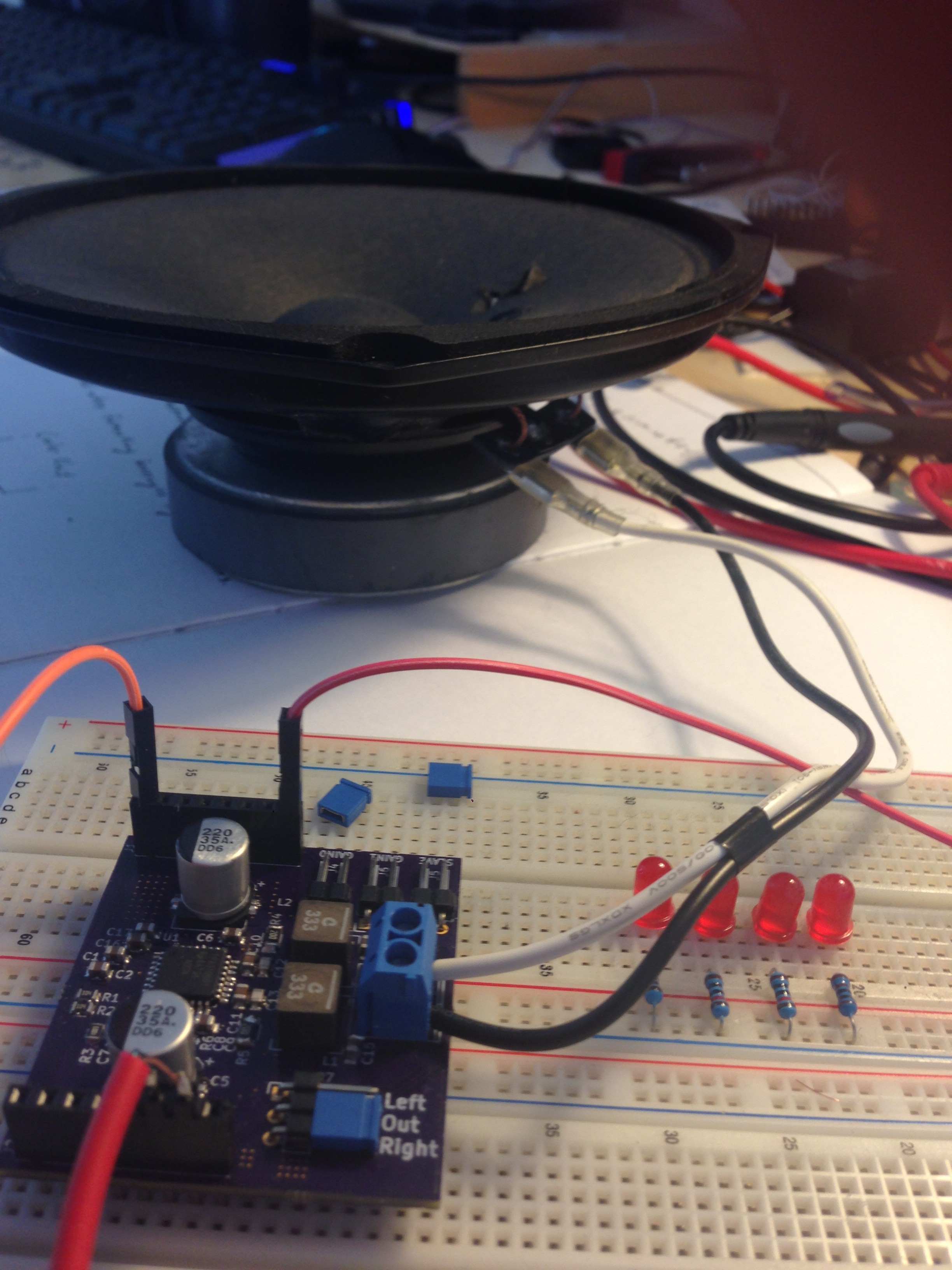
    Fresh boards hot off the press, shout out to OSH park for their awesome work!!! Just ordered up the parts to pop on Digikey, looking like it's going to be less the $10 when the whole thing is said and done. I have extras if anyone is interested, drop me a line!!

    Stokes to get going on the power distribution board!

    Walker