 Blecky
The MappyDot is based on the ST VL53L0X and provides an i2c interface for access to each device. So you might be asking why wouldn't you just use something like the Adafruit VL53L0X breakout board?
Well the MappyDot is more than just the VL53L0X sensor on a board. For starters, the VL53L0X itself is a 1D measurement, i2c device with a single fixed address. So you would need multiple i2c transceivers on your microcontroller to run more than one VL53L0X sensor for full spherical environment measurement or building an air piano. Alternatively you could use an i2c bus multiplexer or follow ST's app note, but this requires additional addressing pins or separate i2c control commands. However, multiplexing adds a lot of complexity to designs, only operate up to 8 devices each, makes it difficult to integrate into a long bus, and it also adds undesirable device switching and control/measurement delays.
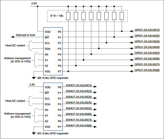
ST's App Note for connecting multiple VL53L0X sensors.
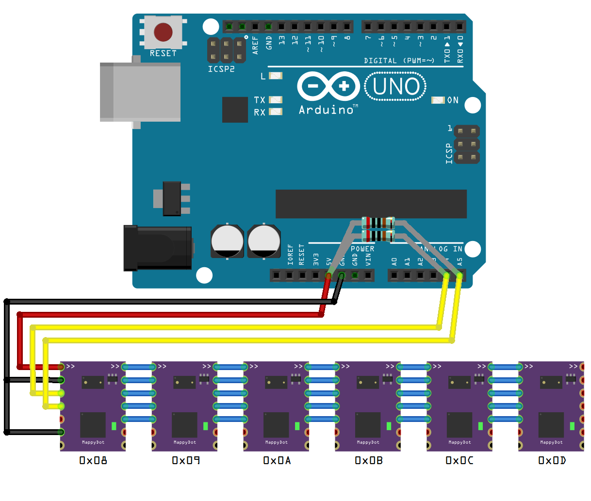
The MappyDot overcomes this by using onboard logic that auto-configures a different i2c address for each device in a chain, which makes them accessible from a single i2c master. This allows you to address up to 112 devices on a single bus:
MappyDots also enable constant measurement and (optional) averaging functions which reduces distance setup and read latency, while increasing accuracy and measurement speeds at no additional processing cost.
Each MappyDot is easy to set up. There's no special libraries to import or functions to program, all you need to do is perform an i2c read on the address/device you require and it will give you the distance measurement instantly as a two byte value. This is perfect for integration with existing robotics or autopilot hardware with minimal fuss or program storage requirements. The default operating mode also switches automatically to the optimal parameters required for different environments.
If you require more advanced configuration options, the MappyDot also gives you access to all the low level operating modes and control for the VL53L0X sensor. So it's great for more advanced applications.
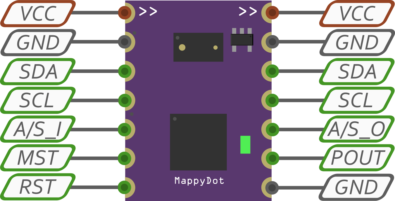
The MappyDot is a tiny module only 12.70x17.48 mm (0.50x0.69 inches) in size. It provides standard 2.54mm (0.100") header locations which can accommodate either pin headers or SMD soldering for integration into new or existing hardware designs. MappyDots operate between 2.8 and 5.5V, so there's no need to worry about whether it will work with your platform of choice.
There's also an onboard LED which can be configured to light up when certain threshold values are reached, when the MappyDot is read for sci-fi cred, or manually controlled to identify each sensor.
Discussions
Become a Hackaday.io Member
Create an account to leave a comment. Already have an account? Log In.
That's how that sensor should have looked like by default. I'm not sure about the automatic address setup (I'm old-school and would prefer jumpers on the back.), but otherwise it's all a great idea. Say, what microcontroller are you using on it?
Are you sure? yes | no
I guess I could think about having jumpers, however you can start the addressing at any value by connecting the ADDR pin of the first device to your dev board and sending it the addressing sequence. I'd like to say which micro, but the one I'm testing with currently isn't the one on the final design, and that's currently having its PCB being made up so I'm not 100% sure about that yet (I'm testing two different price points). It's definitely Atmel AVR based.
Are you sure? yes | no