Elliot Williams
-
PCBs and Code on the GitHubs
06/26/2017 at 21:00 • 0 commentsI've had a good time playing around with LEDs. I've even made up a couple of experimental PCBs. And now I've dumped it all to the EverLED project's GitHub.
The PCB has an inline ISP programming "port" that I use sometimes: Reset, GND, VCC, SCK, MISO, MOSI from top to bottom. It's easier to route into a one-sided design than the 2x3 standard configuration. You might want an adapter, or to change the PCB yourself. :)
If not, there's a PDF suitable for laser-printer toner-transferring (it's mirrored already) and there's a .hex file suitable for flashing.
![]()
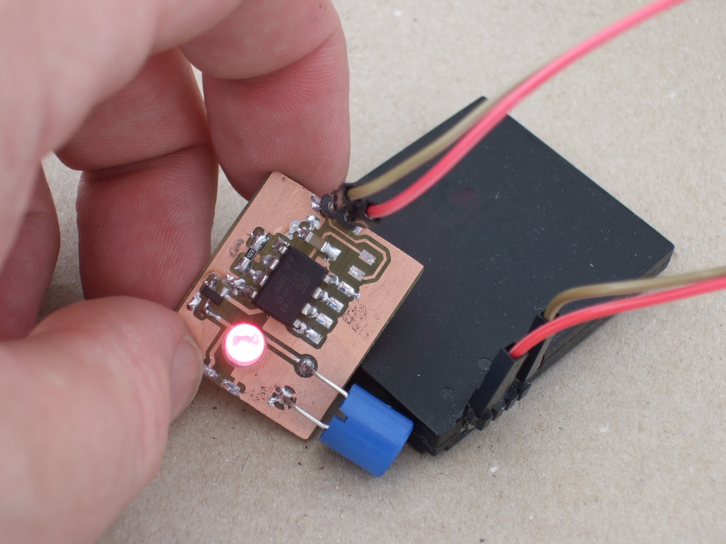
Thumb and fingers for scale.
The ultra-bright red LED shown here is pretty bright when looking directly at it, but almost invisible from the sides. I'm cheating here and pointing it at the camera -- it's a lot dimmer when it's diffused.
Needless to say, the 900 mAh LiIon battery show here is just for testing. In theory, that's 10 years' worth of dim LED. In practice, self-discharge and sheer boredom will dominate, and something smaller makes more sense.
What's next? With an application that only needs 10's of microamps, it makes power harvesting look interesting. I'll probably also make a small, finished version of the PCB, with a SMD ATtiny and everything compacted up. Or maybe a pushbutton...
But if you're interested in playing along, go to it! Everything in the GitHub is tested and works for me. Let me know if it doesn't work for you.
-
Current and Inductors
06/26/2017 at 13:31 • 0 commentsBuilt a couple more of these over the weekend, and even whipped up a quick and dirty PCB. I'm thinking of pouring something permanent and waterproof around them, like clear epoxy resin for fiberglass or something, and we'll see if they get the two year's runtime.
I still hadn't really answered the question of how long a pulse is too long, other than by "feel". So I added a resistor (1,775 ohms -- it was in the box) between the light's ground and "real" ground and scoped out the current flowing through the circuit.
![]()
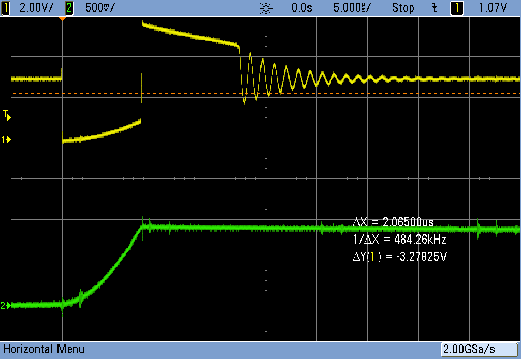
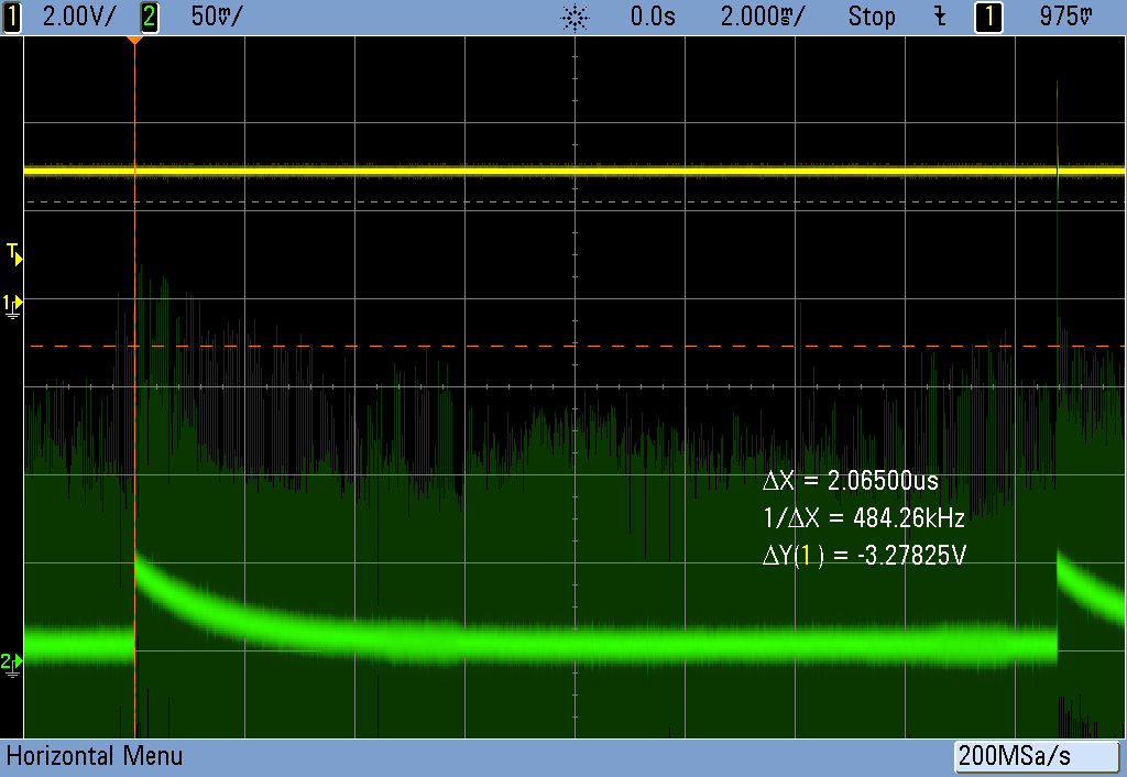
Running for 8 us, you can see the inductor "charging up" in the green trace, and you can also see the power line starting to sag as the "ground" gets pulled up during the transistor's on time in the top graph.
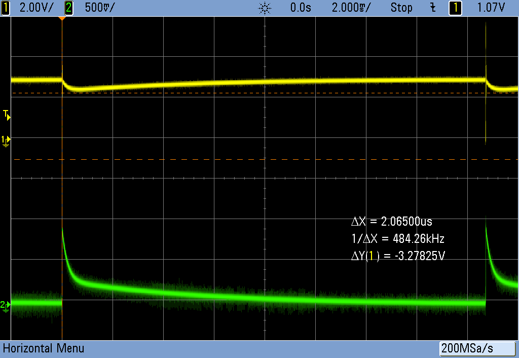
On a cycle-length timescale, changing the yellow trace to the 3.3 V input supply, you can see it getting pulled down and slowly recovering over time. In current (green), the quick peak is the inductor loading up, and the rest is the on-board decoupling capacitor re-charging.
![]()
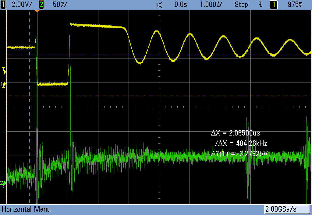
Meanwhile, with 1 us pulses, everything is basically well-behaved again. The current just begins to ramp up before it gets turned back off, storing a relatively small amount of energy, but also not pulling down hard on the voltage rails -- evidence is the flat bottom to the LED voltage (yellow) curve.
![]()
On this scale, the CPU's spikey power demands are visible, and you can also see that it's nowhere near the "fully loaded" zone. That's where I'm running it, and that's about 10 uA total average current draw.
On the cycle time scale, you can see that the voltage rail (here in yellow) doesn't really sag all that much, and that the buffer/decoupling cap on the board charges back up to nominal fairly quickly, leaving only the small, constant draw from the microcontroller.
![]()
The conclusion? With these inductors (labelled 0.1 mH) something in the 1-3 microsecond range looks about "right" and drives nearly any LED dimly, with a current consumption of 10-15 uA. I guess I knew this before, but it's reassuring to see measurement match intuition.
Think of the inductor in this circuit as a time-dependent resistor. When you pulse on, it has maximum "resistance", and this decreases as it charges up its mag field. So if you use a larger inductor, you can store more energy while still staying in the high-resistance part of the curve, but you'll have to leave the pulse on longer. Or vice-versa: if you want to pass more energy, and don't want to draw excessive current pulses, you'll want a larger inductor.
Anyway, now I'm probably actually done with this circuit. 10 uA is sufficiently low that it'll run for years on a coin cell, and bright or dim enough with the choice of the right LED. The AVR will run up to 6 V, and doesn't seem to crap out until around 1.2-1.4 V, so power is not a problem. Energy-harvesting, anyone?
If you mess around with the code and find a modulation mode that you like, let me know in the comments?
I'll post up my (KiCad) PCB files in a GitHub just for completeness, although there's not that much to these things.
Enjoy!
-
Schematic
06/23/2017 at 21:33 • 1 comment![]()
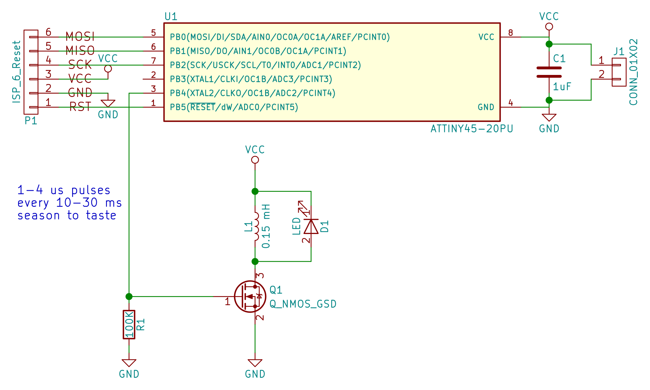
The only interesting part of the project is the FET, inductor, and LED. The rest is just making pulses while using as little power as possible. This is not much of a circuit. Values are what I used, but are probably only really good as a starting point.
Capacitor on the power rail is very necessary. When you crowbar the power rail through the inductor, it makes a predictable sag. I ran it for a while without, and the chip reset with every pulse. Doh!
Also necessary is the pulldown on the FET. If it opens for more than a few microseconds, the inductor acts as a short to ground and it gets very hot. In your hand. As you're trying to program the darn thing.
Anyone wanna bet on how much more/less power a CMOS oscillator and pulse-shaper would use than the AVR?
-
Build First, Think Second
06/22/2017 at 20:46 • 1 comment![]()
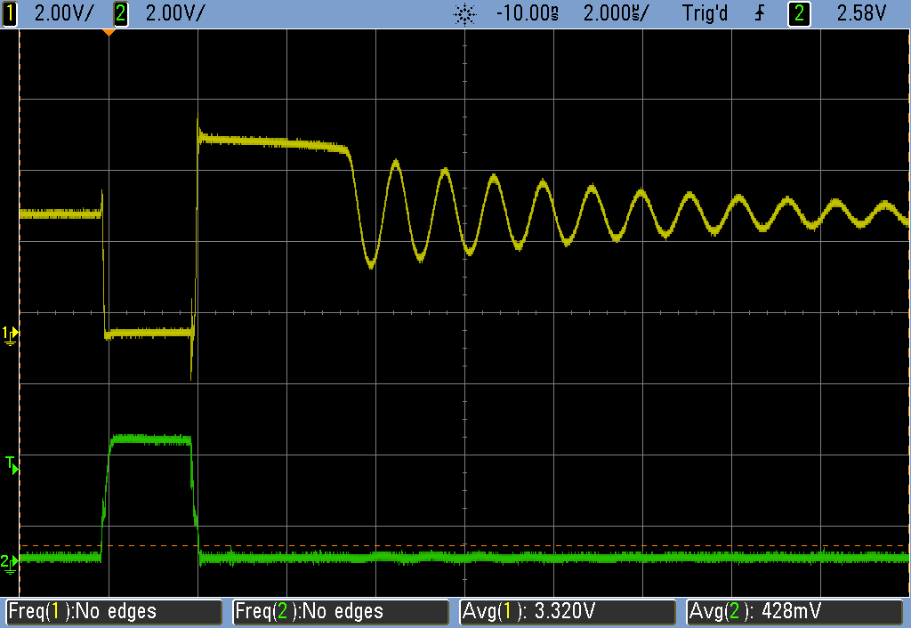
So here's how this works. The yellow trace is the voltage at the + pin of the LED (the low side of the inductor), and the green is the "one microsecond" pulse from the AVR, that really looks like two microseconds, huh?
The AVR turns on the MOSFET, dropping the low side of the inductor from 3.3 V (battery voltage) to zero. Current is running through the inductor. The FET turns off, and current wants to keep running through the inductor, building up a voltage until it's high enough (here a ~2 V LED + 3 V battery) to light the LED.
The LED lights up for about 3.5 usec and then dips under its threshold and does that funny oscillating thing. Would an LED with a lower threshold have smaller amplitude oscillations, and waste less energy? I have no idea how much energy is represented by the wiggles -- my guess is that, with a low-resistance inductor, it's doing very little work = not much.
The AVR sleeps for 16 milliseconds -- an eternity on this timescale -- and it all repeats.
For a given inductor/LED, what is the optimal pulse width? What I want, but haven't figured out yet, is to measure the current through the inductor and figure out when it's "full". You can do that empirically by changing the AVR's on-time and noticing how the LED's on time-responds because that corresponds to the energy stored in the inductor's field. Beyond something like 4 microseconds, the on-time doesn't seem to lengthen all that much, so maybe 2 microseconds is a lucky guess.
I could add in a resistor and measure voltage drop, I suppose.
Putting two LEDs in series, the max voltage goes up to ~7-8 V, or 3 V + 2x LED threshold voltages.
If you use a larger inductor but a fixed pulse length, the current draw drops, which makes sense because it "charges up" more slowly -- equivalently it displays more reactance. I'm not sure if I should be thinking in the time or frequency domains here...
-
Wait a Minute!
06/22/2017 at 13:37 • 4 commentsWhat the heck am I doing? The whole point of the flyback/inductor trick is to make a step-up voltage converter, and I'm running a 1.8 V LED off of a 3.3 V battery...
Well, whatever it's doing (providing more reactance?) it's doing a good thing: pulling the inductor out and just driving the LED straight burns 60 microamps. It may also be a fair bit brighter, but that's not really the point of this exercise.
I called this done, and now I need to play around with the circuit some more. Sigh.
---------------
Edited to include Ted's constant-current comparison: one LED, one datapoint.
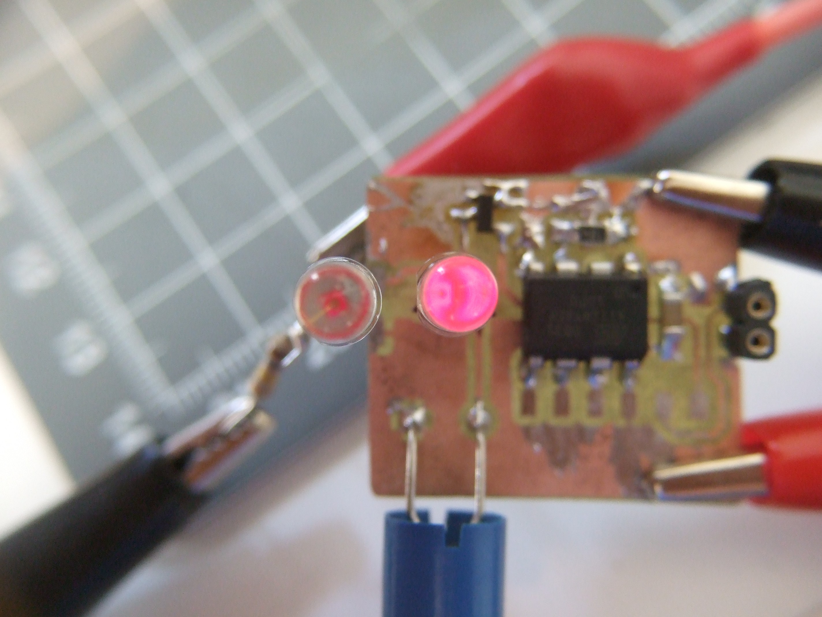
![]()
Two LEDs from same tape reel. Left driven at constant 11.1 microamps through a 150k resistor. Right driven by pulse circuit at 9.1 microamps (including the ~5 microamps eaten by the AVR and transistor -- so maybe 4 uA avg for the LED).
I couldn't even tell that the left LED was on until I cupped my hand around it, as I'm doing in this image. The difference looks about like this to my eyes as well -- they're strikingly different. One is "bright" and the other is barely on.
As Ted points out, running the LED with milliamp peaks seems to make them run a lot brighter. Woot.
Neither of these will illuminate anything, mind you. In a dark room, you can see the brighter LED easily, but it's not throwing enough light to read by or anything. Still, if you just want a marker, it's perfect.
-
Quick Test, AVR Power Optimization, Done!
06/22/2017 at 10:03 • 0 commentsTed uses a 1 mH inductor, but I only had 0.15 mH. Ted uses a particular high-wattage LED. I had a regular "ultra" amber LED from a surplus store. Ted uses a low-power microcontroller. I had an ATtiny45. Would it blend?
The first tests were just the pulses, and sure enough the theory works just fine -- super-short pulses "charged up" the inductor and let it dump back through the LED. Alone (with 4 us pulses every 20 microseconds) it was running 4 microamps.
Adding in the ATtiny45 with busy-wait loops and no power optimization used up ~500 microamps. Well, that won't work.
Best thing to do? Turn off everything possible -- power_all_disable() from avr/power.h -- and put the pin-toggling code into an interrupt that fires off the watchdog timer. That way the ATTiny45 is sleeping in full power-down mode for 99.99375% of the time. Not a low-power chip when it's on, but who cares?
I also shortened the pulse duration down to ~1 microsecond, because it still looked bright enough to see at night, and I couldn't go any faster.
Et voila! 10 microamps (9.9, but who's counting?) running. Or about 2.5 years on a coin cell, nominally.
Could it be brighter? I presume so. Ted's research on optimal LED drive currents would be the place to go. Or I could just use longer pulses, which seem to do the trick.
Could it use less power? Maybe. I didn't particularly optimize the size of the inductor.
The FET (IRLML 6244) is pretty good for the application. Turns on and off quick at 3 V, has low on resistance. I don't think that could be significantly improved on.
And that's it. It's not refined like Ted's, but I built it and it works. I'll might play around with different LEDs or inductors, but maybe later. Right now, I just want you to know that although one can polish a simple design like this until it shines, it also works well enough with whatever you've got on hand.