Close
0%
0%

Freeformed Astable Multivibrator

This is a classic circuit that blinks two LEDs back and forth

Similar projects worth following
I've spent a lot of time learning about microcontrollers and very little time working with analog electronics. Wanting to change that, the first circuit I've been exploring is the Astable Multivibrator. It's a set of RC time constants connected to each other, as one charges, it triggers a transistor that discharges the other. The system is never stable so the result is lights tha flash in an alternating pattern.

Note: This project has been submitted to the 2017 Hackaday Prize but it is not eligible for judging since it was built by a member of the Hackaday staff. The project was submitted as a way to test out and make tutorials for other people to use as a guide when working on their Prize entries.

This project uses very few components to build a clever little analog blinker.


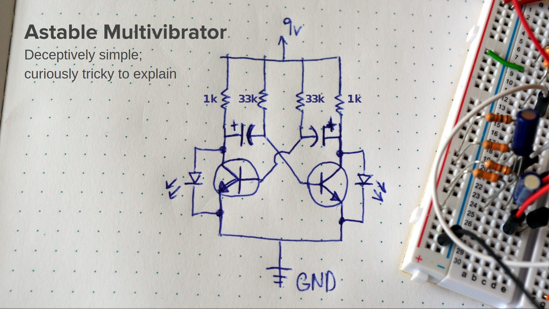
If you compare this schematic with the main image of the soldered version you can see it is the perfect circuit to solder without a circuit board since it's possible to lay everything flat with only one place where two wires cross.

For assembly I simply used the leads of the components with no added wire. I did take a piece of the insulation off of some wire to protect against a short where the two wires cross in the middle of the assembly.

Here's a demo of the circuit running:

And you might find it interesting to see the circuit simulation:

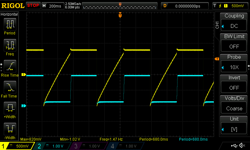
The oscilloscope output clearly shows the ramp of the base of one of the transistor and the square wave that results on one of the LEDs:

Bill of Materials

https://www.findchips.com/org/10-open-hardware/list/35514-astable-multivibrator

    QTY Part Number Description
    2 1k Resistor
    2 33k Resistor
    2 47 uF Electrolytic Capacitor
    2 LEDs Electronic Components / Misc. Electronic Components
    1 9v Battery Connector

  • Get a 9V Connector from a Dead 9V

    Mike Szczys03/06/2020 at 17:37 0 comments

    If you're powering a project from a 9V battery, you can salvage a suitable connector from a dead 9V.

    Grab your bucked of dead batteries and search through it for 9V

    Choose one that doesn't have a buildup of blue corrosion on it

    Remove the sheet metal case being careful not to cut yourself. This battery has flat cells in it, but occasionally you'll find six cylindrical cells. There will always be six of them because each cell adds 1.5V to the overall output.


    Liberate the connector for your own purposes. Soldering wires to these can be a challenge. I recommend roughing up the surface first with a dremel or coarse sand paper and adding a blob of solder before trying to connect a wire or component lead.

View project log

Enjoy this project?

Share

Discussions

Dr. Cockroach wrote 03/06/2020 at 22:50 point

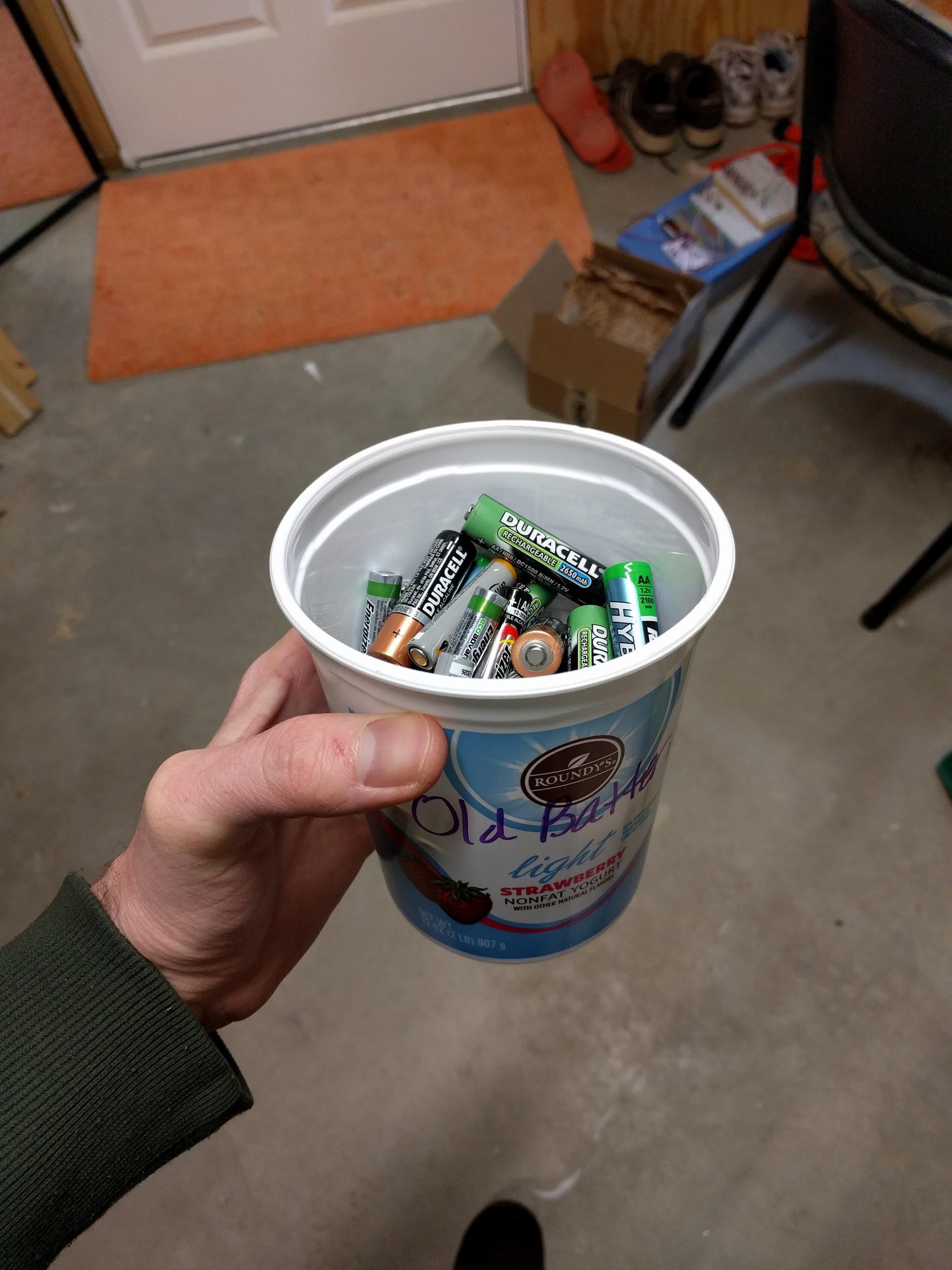
I had never given thought to re-using the contacts from a dead batt but will give it a try someday. I have always admired the form and circuit of a Astable, it just seems like like a art form in itself. It even works with  a pair of Light Logic switches used instead of the transistors :-)

  Are you sure? yes | no

Giulio Pons wrote 11/20/2019 at 20:34 point

I've made a multivibrator astable as your, why when battery voltage fall down the frequency change? The lowest the voltage, the higher the frequency is. When it goes down a lot it also seems that both leds are simultaneously on with very low light.

  Are you sure? yes | no

Similar Projects

Does this project spark your interest?

Become a member to follow this project and never miss any updates