 Mo Badr
Features (stepZeroR1)
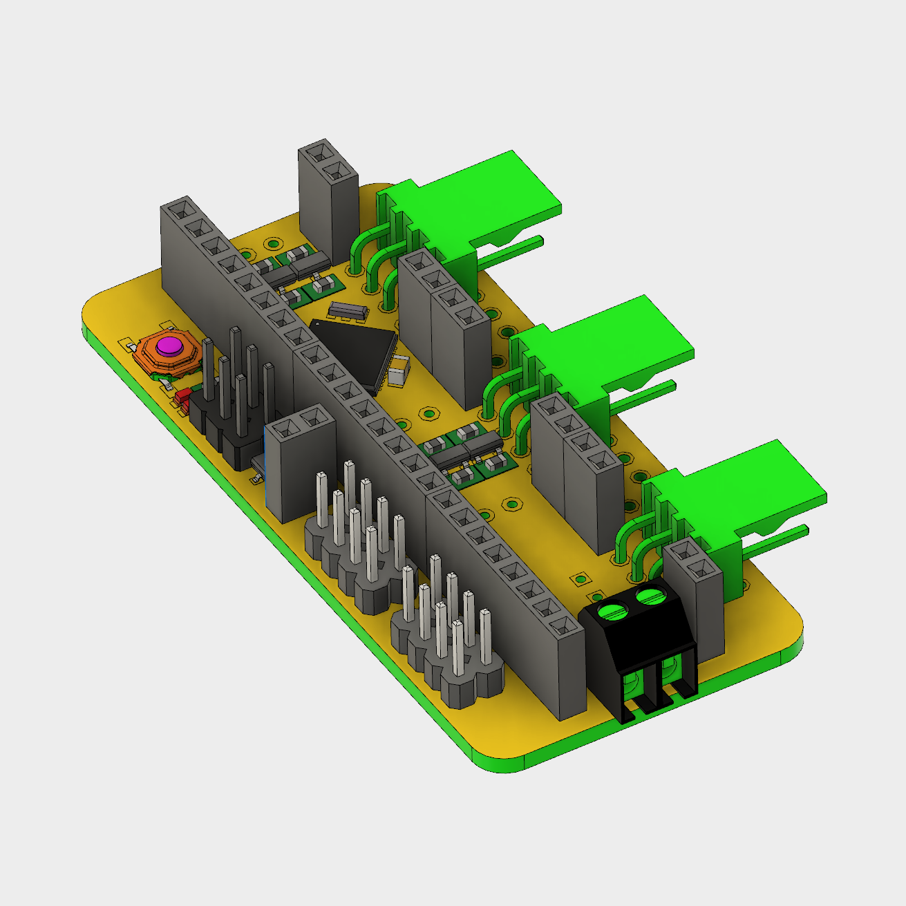
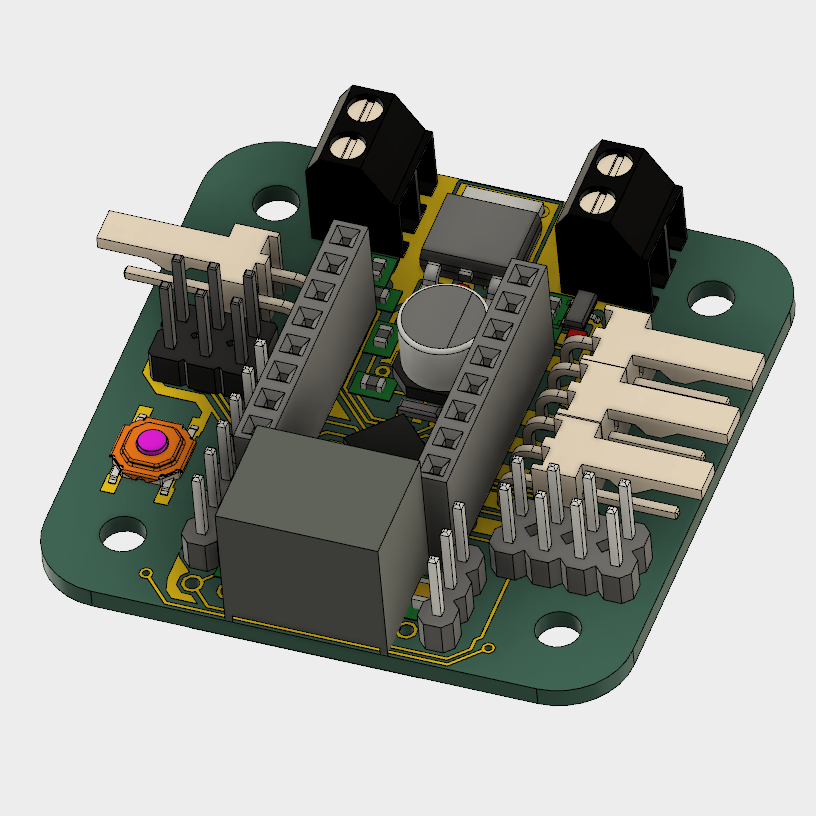
- ATmega1284p Sanguino (Arduino compatible) core running at 20MHz
- Switching regulator DC-DC converter to power the RPi (1.5A OKI-78SR)
- Communicates to RPi via UART to upload firmware and connect to OctoPrint
- Headers for three StepStick stepper drivers (micro step adjusted via solder jumbers)
- Connectors for three end stop limit switches
- Four expansion ports (I2C based) for driving extruders, heated bed, spindle, etc

 derethor
 Uriel Katz
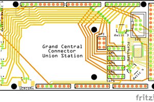
 bobgreenwade
 Alastair Young
You should check out https://github.com/KevinOConnor/klipper for software juiciness.